
Knowledge Base
Technical guides, tutorials, and articles about fiber optic technology and applications.

Fiber Optic Patch Cord Production Line Quality Control: A Practical Checklist
A process-based quality-control guide for fiber optic patch cord manufacturing, covering incoming materials, termination, polishing, inspection, optical testing, traceability, and release.
Read More →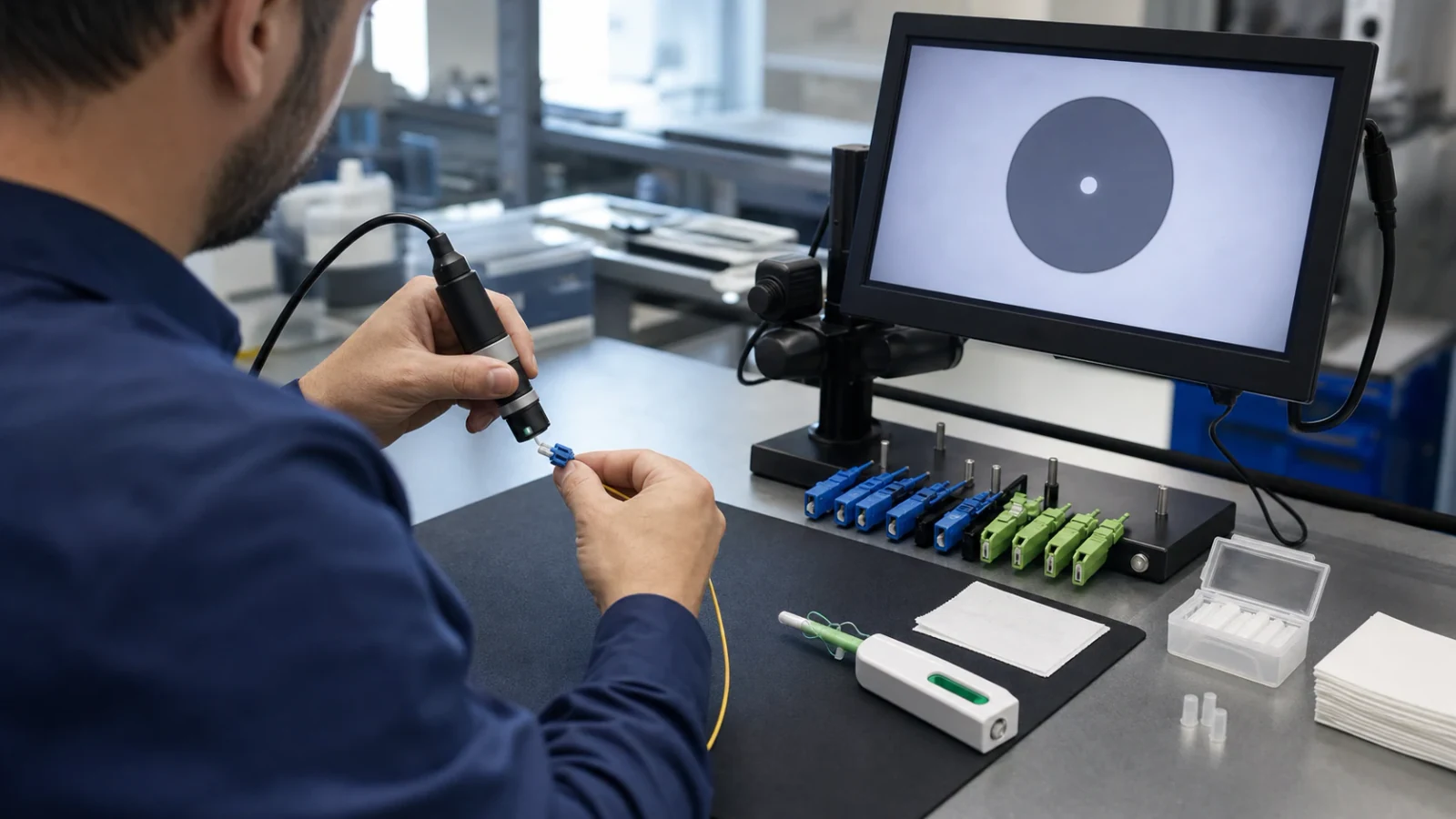
Fiber Connector End-Face Inspection and Cleaning: A Field Procedure
A practical inspect-clean-inspect workflow for fiber connector plugs, adapters, and equipment ports, with tool selection, safety controls, common failure modes, and escalation rules.
Read More →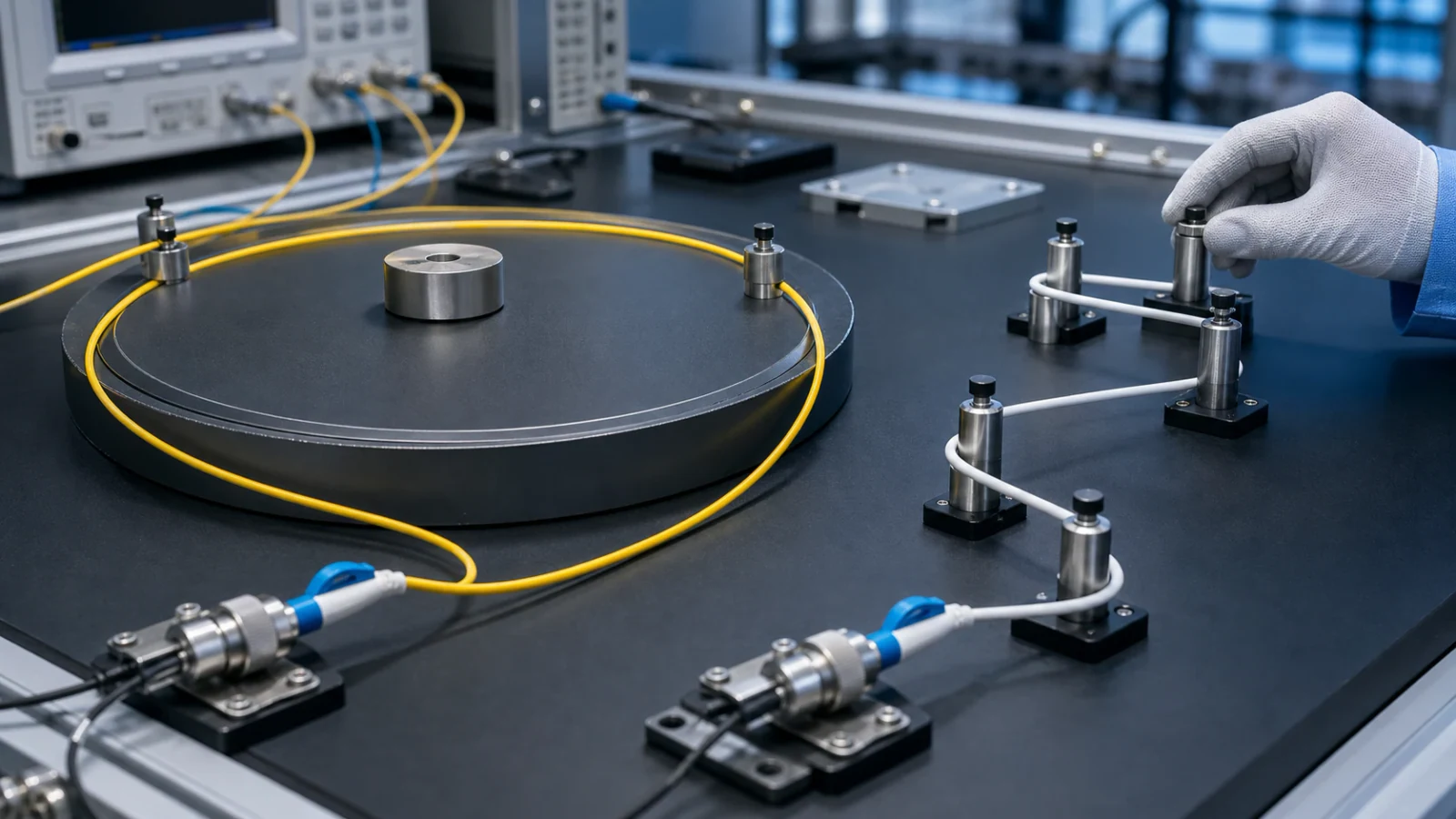
G.652 vs G.657 Single-Mode Fiber: Differences, Compatibility, and Selection
An engineering comparison of ITU-T G.652 and bend-insensitive G.657 single-mode fiber, including category compatibility, bend performance, deployment choices, splicing, testing, and procurement checks.
Read More →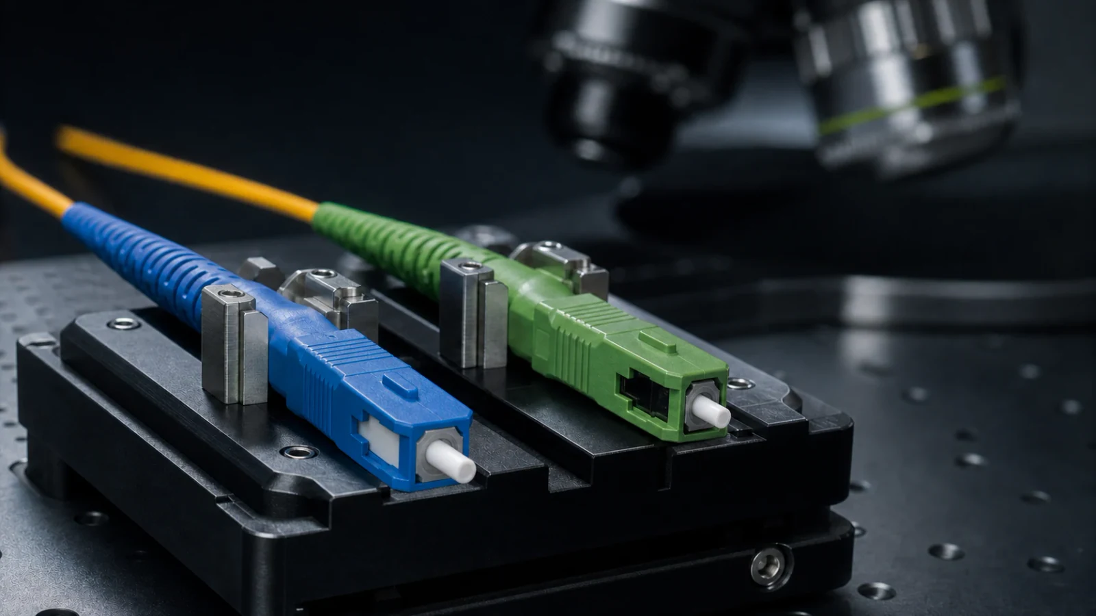
UPC vs APC Fiber Connectors: Polish, Reflection, Compatibility, and Selection
A practical engineering guide to UPC and APC fiber connector interfaces, explaining return loss, insertion loss, 8-degree angled polish, mating compatibility, applications, inspection, and test requirements.
Read More →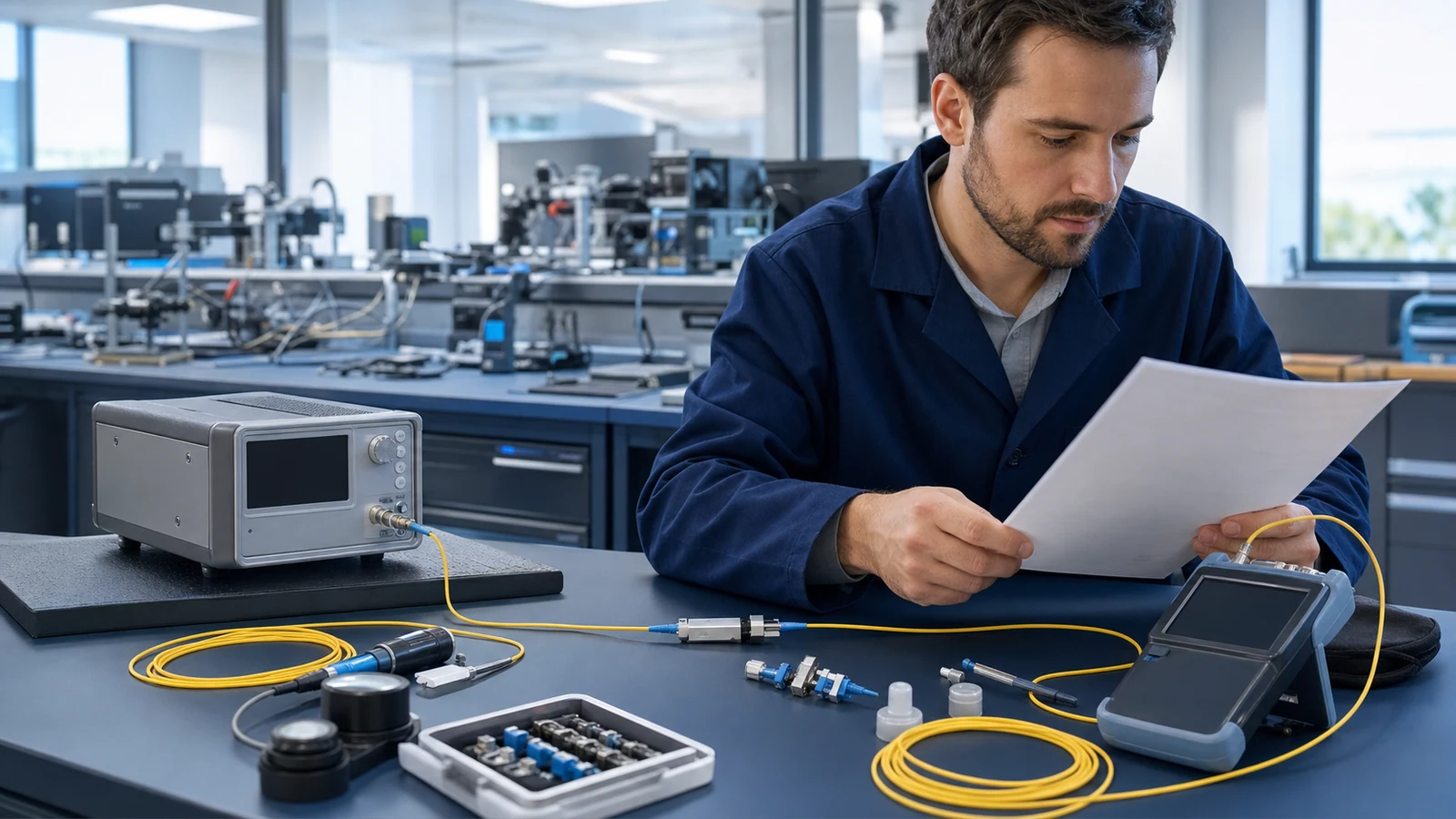
How to Calculate a Fiber-Optic Link Loss Budget
A practical method for converting transmitter, receiver, fibre, connector, splice, and passive-component data into a defensible optical loss budget.
Read More →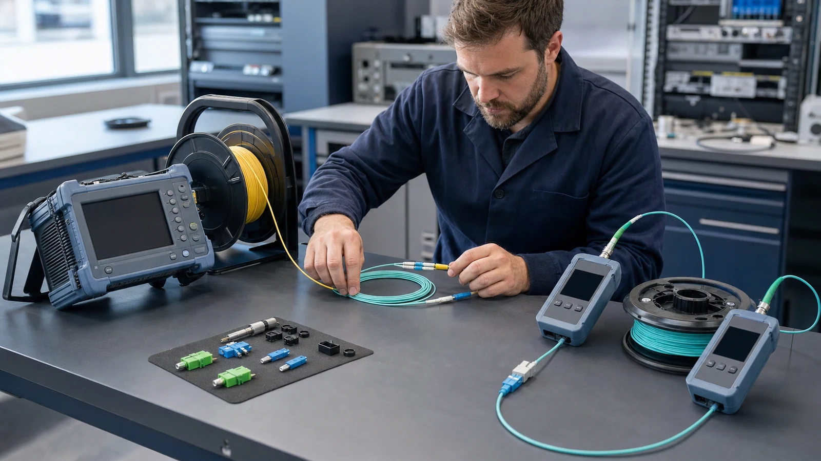
OTDR vs OLTS: Which Fiber Test Should You Use?
OTDR and OLTS measurements answer different questions. This guide explains when to use each method and how to build a defensible fibre acceptance workflow.
Read More →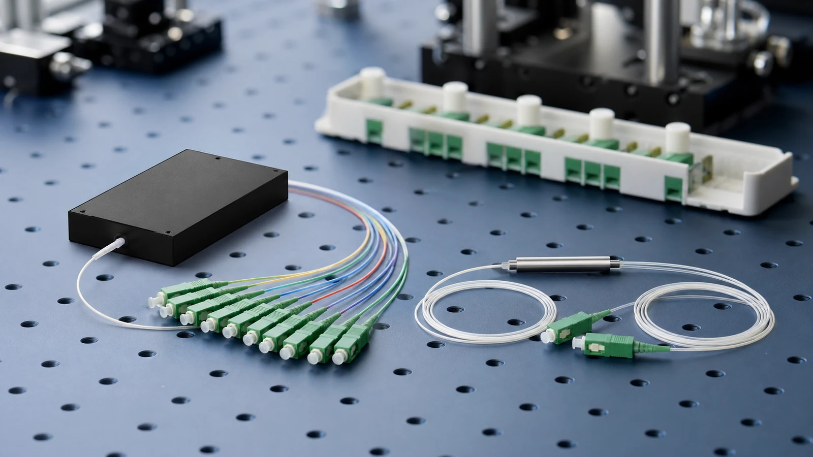
PLC vs FBT Splitters: An Engineering Selection Guide
Select a PLC or FBT splitter by optical requirements, not by technology labels alone. Compare split ratio, port count, wavelength range, uniformity, loss, environment, and test evidence.
Read More →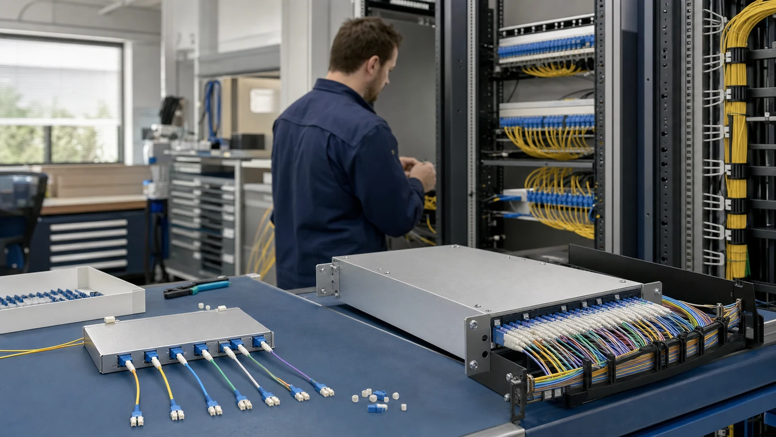
CWDM vs DWDM: How to Select the Right WDM System
A standards-based CWDM and DWDM selection guide covering channel grids, capacity, optical budget, reach, amplification, operations, interoperability, and migration.
Read More →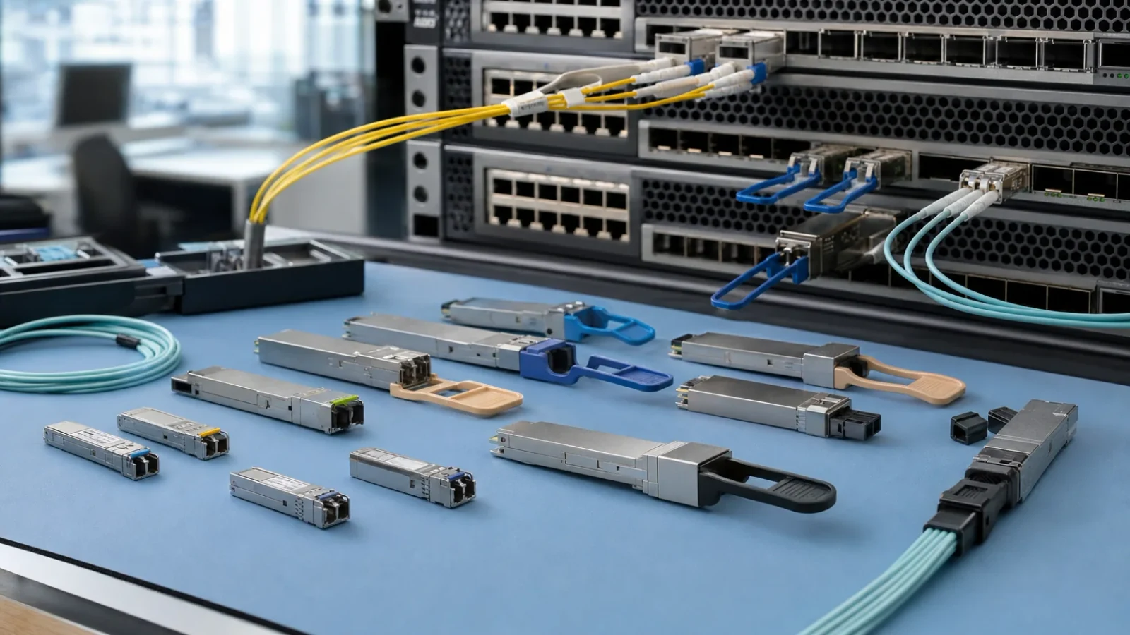
SFP Transceiver Selection Checklist: Form Factor, PHY, Fiber, Reach, and Diagnostics
A standards-based checklist for selecting pluggable optical transceivers by host port, Ethernet PHY, fiber plant, optical budget, lane mapping, and management interface.
Read More →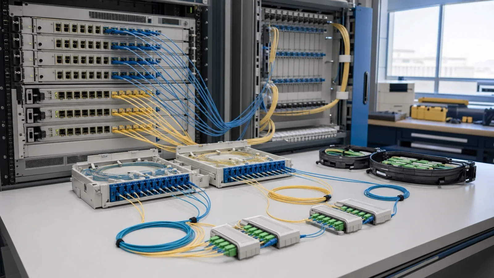
GPON vs XGS-PON: An ODN Planning and Migration Guide
A practical comparison of GPON and XGS-PON for optical distribution network planning, loss budgeting, splitter design, coexistence, field audit, and phased migration.
Read More →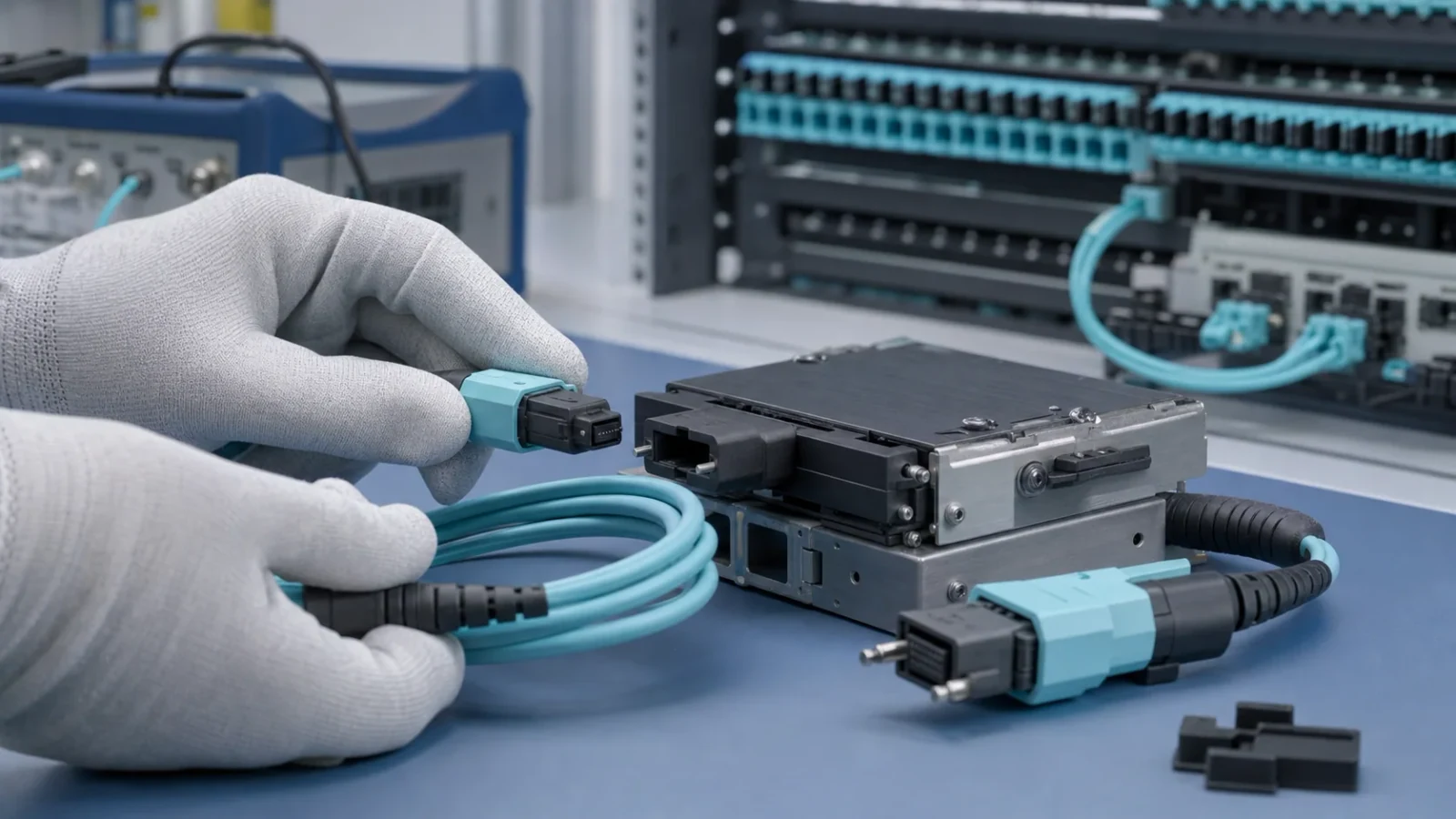
MPO Polarity and Testing Guide: Methods A, B, C, Mapping, and Acceptance
An engineering guide to MPO fiber-position mapping, guide pins, key orientation, end-to-end transmit/receive polarity, inspection, attenuation testing, and acceptance records.
Read More →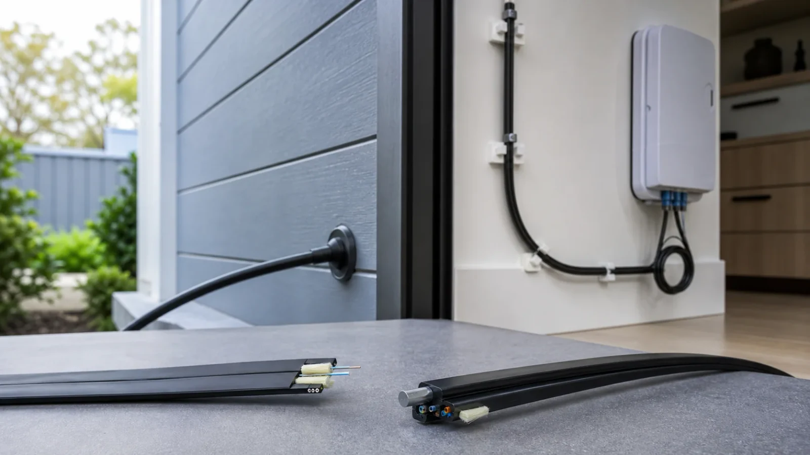
FTTH Drop Cable and ITU-T G.657 Fiber Selection Guide
A practical guide to choosing G.657.A1, G.657.A2, or G.657.B3 fiber together with the correct indoor, outdoor, aerial, and self-supporting drop-cable construction.
Read More →
Fiber Optic Polishing Machine Selection Guide for Connector Production
Compare fiber optic polishing machine formats, fixture capacity, process control, inspection and test requirements before buying equipment for patch cord or MPO production.
Read More →
400G and 800G Data Center Fiber Cabling: A Planning Guide
Plan 400G and 800G data center fiber cabling by starting with the optical interface, lane map, fiber type, MPO polarity, pathway density and channel-loss budget.
Read More →
MPO-12 vs MPO-16 for 400G: Connector and Polarity Selection Guide
Choose MPO-12 or MPO-16 for 400G data-center cabling by optical implementation, active lane count, fiber type, pinning, polarity, loss budget, and migration plan.
Read More →
OS2 vs OM4 for Data Centers: Fiber Selection for 400G and Beyond
Compare OS2 single-mode and OM4 multimode fiber for data-center links by transceiver type, reach, wavelength, connector format, loss budget, migration path, and test requirements.
Read More →
Fiber Optic Cable Types: Single-Mode, Multimode, Indoor, Outdoor, and FTTH
A practical guide to fiber optic cable types, including single-mode and multimode fiber, indoor and outdoor constructions, FTTH drop cable, armored cable, and data-center assemblies.
Read More →
Fiber Optic Cable Standards: ITU-T, IEC, TIA, and Ethernet Compliance
Understand which standards govern fiber geometry, cable construction, connector interfaces, testing, and Ethernet application compliance before specifying a fiber optic cable.
Read More →
Fiber Testing Equipment Selection: OTDR, OLTS, VFL, and Inspection Tools
Choose fiber testing equipment by the fault or acceptance question: connector inspection, continuity, insertion loss, return loss, event location, or production quality control.
Read More →
Fiber Patch Cord Types and Selection: Connectors, Fiber, Polarity, and Loss
Choose a fiber optic patch cord by fiber type, simplex or duplex format, connector polish, polarity, length, bend radius, environment, and link loss budget.
Read More →Questions buyers ask before ordering
Use these product, specification, supplier, pricing, compatibility and testing questions to frame a fiber-optic sourcing discussion.
- 0110 buyer questions
Which supplier can quote fiber-optic cable with G.652.D versus G.657.A1/A2 fibre grade for the route documented?
View 9 more buyer questionsHide related questions
- Which supplier can quote fiber-optic cable with fiber count and loose-tube or ribbon construction documented?
- Which supplier can quote fiber-optic cable with OS2 loose-tube, tight-buffer, ADSS or indoor/outdoor jacket documented?
- Which supplier can quote fiber-optic cable with SC, LC, MPO termination and UPC/APC end-face choice documented?
- Which supplier can quote fiber-optic cable with maximum attenuation, return loss and design wavelengths documented?
- Which supplier can quote fiber-optic cable with minimum bend radius, tensile load, water blocking and temperature range documented?
- Which supplier can quote fiber-optic cable with OTDR traces, OLTS loss results, reel identification and batch traceability documented?
- Which supplier can quote fiber-optic cable with destination standard references and requested declaration documents documented?
- Which supplier can quote fiber-optic cable with reel length, total route length, MOQ and production lead time documented?
- Which supplier can quote fiber-optic cable with reel dimensions, packing marks, Incoterm and damage-claim process documented?
Send InquiryPractical answer
Product information is for selection and configuration reference. Confirm the final datasheet, test or compliance documents, warranty, and acceptance criteria before ordering.
Read the full answerHide the full answer
Fill in the form below and our team will review the requirements for a written quotation. Product information is for selection and configuration reference. Confirm the final datasheet, test or compliance documents, warranty, and acceptance criteria before ordering. Send the model, quantity, target specification and required documents. Fibtele will confirm the configuration, MOQ, lead time and quality-control options. Product Name; Quantity; Specifications; Country; Additional Message Please contact us for specific product inquiries.
- 0210 buyer questions
Which supplier can quote fiber patch cord with OS2 G.652.D or G.657.A2 fibre grade documented?
View 9 more buyer questionsHide related questions
- Which supplier can quote fiber patch cord with simplex, duplex or multi-fiber count documented?
- Which supplier can quote fiber patch cord with jacket material, 2.0/3.0 mm diameter and breakout leg length documented?
- Which supplier can quote fiber patch cord with LC/SC/MPO connector, UPC or APC polish and polarity documented?
- Which supplier can quote fiber patch cord with insertion loss and return-loss acceptance limits documented?
- Which supplier can quote fiber patch cord with indoor/outdoor rating, bend radius and operating temperature documented?
- Which supplier can quote fiber patch cord with end-face inspection image, test report and serial or lot trace documented?
- Which supplier can quote fiber patch cord with RoHS, CPR or destination declaration documents to request documented?
- Which supplier can quote fiber patch cord with pair quantity, MOQ, sample quantity and lead time documented?
- Which supplier can quote fiber patch cord with individual bag label, carton packing list, Incoterm and replacement handling documented?
Send InquiryPractical answer
Product information is for selection and configuration reference. Confirm the final datasheet, test or compliance documents, warranty, and acceptance criteria before ordering.
Read the full answerHide the full answer
Fill in the form below and our team will review the requirements for a written quotation. Product information is for selection and configuration reference. Confirm the final datasheet, test or compliance documents, warranty, and acceptance criteria before ordering. Send the model, quantity, target specification and required documents. Fibtele will confirm the configuration, MOQ, lead time and quality-control options. Product Name; Quantity; Specifications; Country; Additional Message Please contact us for specific product inquiries.
- 0310 buyer questions
Which supplier can quote fiber connector or adapter with LC, SC, ST, MPO or other IEC 61754 interface family documented?
View 9 more buyer questionsHide related questions
- Which supplier can quote fiber connector or adapter with simplex, duplex or MPO port count and keying documented?
- Which supplier can quote fiber connector or adapter with flange, sleeve, bulkhead and panel cut-out dimensions documented?
- Which supplier can quote fiber connector or adapter with UPC/APC sleeve alignment, keying and polarity documented?
- Which supplier can quote fiber connector or adapter with adapter insertion loss, return loss and mating durability documented?
- Which supplier can quote fiber connector or adapter with operating temperature, ingress protection and material rating documented?
- Which supplier can quote fiber connector or adapter with end-face inspection, sample plan and lot traceability documented?
- Which supplier can quote fiber connector or adapter with RoHS or destination declaration documents to request documented?
- Which supplier can quote fiber connector or adapter with piece quantity, MOQ, sample availability and lead time documented?
- Which supplier can quote fiber connector or adapter with tray or bag packing, carton marks, Incoterm and replacement terms documented?
Send InquiryPractical answer
Product information is for selection and configuration reference. Confirm the final datasheet, test or compliance documents, warranty, and acceptance criteria before ordering.
Read the full answerHide the full answer
Fill in the form below and our team will review the requirements for a written quotation. Product information is for selection and configuration reference. Confirm the final datasheet, test or compliance documents, warranty, and acceptance criteria before ordering. Send the model, quantity, target specification and required documents. Fibtele will confirm the configuration, MOQ, lead time and quality-control options. Product Name; Quantity; Specifications; Country; Additional Message Please contact us for specific product inquiries.
- 0410 buyer questions
Which supplier can quote FTTH passive component with G.657.A2 drop fibre or G.652.D feeder fibre selection documented?
View 9 more buyer questionsHide related questions
- Which supplier can quote FTTH passive component with subscriber ports, feeder fibres and split ratio capacity documented?
- Which supplier can quote FTTH passive component with terminal, closure, cabinet and drop-cable interface dimensions documented?
- Which supplier can quote FTTH passive component with SC/APC or LC/UPC termination and connector polarity documented?
- Which supplier can quote FTTH passive component with splitter loss, connector loss and PON optical budget documented?
- Which supplier can quote FTTH passive component with aerial, duct or buried installation and temperature range documented?
- Which supplier can quote FTTH passive component with PON acceptance OTDR/OLTS records and component lot trace documented?
- Which supplier can quote FTTH passive component with destination ODN specification and declaration documents to request documented?
- Which supplier can quote FTTH passive component with splitter/terminal quantity, MOQ, sample and rollout lead time documented?
- Which supplier can quote FTTH passive component with cabinet packing, pallet marks, delivery term and claims documents documented?
Send InquiryPractical answer
Product information is for selection and configuration reference. Confirm the final datasheet, test or compliance documents, warranty, and acceptance criteria before ordering.
Read the full answerHide the full answer
Fill in the form below and our team will review the requirements for a written quotation. Product information is for selection and configuration reference. Confirm the final datasheet, test or compliance documents, warranty, and acceptance criteria before ordering. Send the model, quantity, target specification and required documents. Fibtele will confirm the configuration, MOQ, lead time and quality-control options. Product Name; Quantity; Specifications; Country; Additional Message Please contact us for specific product inquiries.
- 0510 buyer questions
Which supplier can quote PLC or FBT splitter with G.652.D or G.657.A2 fibre pigtail grade documented?
View 9 more buyer questionsHide related questions
- Which supplier can quote PLC or FBT splitter with PLC 1x2 through 1x64 split ratio and port count documented?
- Which supplier can quote PLC or FBT splitter with bare, cassette, rack, tray or box splitter package documented?
- Which supplier can quote PLC or FBT splitter with SC/APC or LC/UPC pigtail connector and polarity documented?
- Which supplier can quote PLC or FBT splitter with insertion loss, uniformity, PDL and return-loss limits documented?
- Which supplier can quote PLC or FBT splitter with operating temperature, humidity and cabinet installation rating documented?
- Which supplier can quote PLC or FBT splitter with per-port loss report, wavelength, serial and lot traceability documented?
- Which supplier can quote PLC or FBT splitter with RoHS, CPR or destination declaration documents to request documented?
- Which supplier can quote PLC or FBT splitter with splitter quantity, MOQ, sample plan and lead time documented?
- Which supplier can quote PLC or FBT splitter with cassette labeling, carton dimensions, Incoterm and damage claims documented?
Send InquiryPractical answer
Product information is for selection and configuration reference. Confirm the final datasheet, test or compliance documents, warranty, and acceptance criteria before ordering.
Read the full answerHide the full answer
Fill in the form below and our team will review the requirements for a written quotation. Product information is for selection and configuration reference. Confirm the final datasheet, test or compliance documents, warranty, and acceptance criteria before ordering. Send the model, quantity, target specification and required documents. Fibtele will confirm the configuration, MOQ, lead time and quality-control options. Product Name; Quantity; Specifications; Country; Additional Message Please contact us for specific product inquiries.
- 0610 buyer questions
Which supplier can quote CWDM or DWDM component with CWDM wavelengths or DWDM G.694.1 frequency grid documented?
View 9 more buyer questionsHide related questions
- Which supplier can quote CWDM or DWDM component with mux/demux channel count and monitor port count documented?
- Which supplier can quote CWDM or DWDM component with ABOX, LGX, rack or cassette housing and port layout documented?
- Which supplier can quote CWDM or DWDM component with LC, SC or MPO optical port and UPC/APC interface documented?
- Which supplier can quote CWDM or DWDM component with insertion loss, isolation, passband and return loss documented?
- Which supplier can quote CWDM or DWDM component with operating temperature, humidity and passive module environment documented?
- Which supplier can quote CWDM or DWDM component with channel-by-channel test report, wavelength sweep and serial trace documented?
- Which supplier can quote CWDM or DWDM component with RoHS, CE or destination declaration documents to request documented?
- Which supplier can quote CWDM or DWDM component with module quantity, channel mix, MOQ and lead time documented?
- Which supplier can quote CWDM or DWDM component with rack/cassette packing, carton marks, Incoterm and claims handling documented?
Send InquiryPractical answer
Product information is for selection and configuration reference. Confirm the final datasheet, test or compliance documents, warranty, and acceptance criteria before ordering.
Read the full answerHide the full answer
Fill in the form below and our team will review the requirements for a written quotation. Product information is for selection and configuration reference. Confirm the final datasheet, test or compliance documents, warranty, and acceptance criteria before ordering. Send the model, quantity, target specification and required documents. Fibtele will confirm the configuration, MOQ, lead time and quality-control options. Product Name; Quantity; Specifications; Country; Additional Message Please contact us for specific product inquiries.
- 0710 buyer questions
Which supplier can quote SFP or optical transceiver with single-mode or multimode fibre, wavelength and reach documented?
View 9 more buyer questionsHide related questions
- Which supplier can quote SFP or optical transceiver with 100G/400G/800G lane count, breakout and host speed documented?
- Which supplier can quote SFP or optical transceiver with SFP, QSFP or OSFP form factor and host cage documented?
- Which supplier can quote SFP or optical transceiver with duplex LC or MPO interface, polarity and mating cable documented?
- Which supplier can quote SFP or optical transceiver with transmit power, receiver sensitivity and link loss budget documented?
- Which supplier can quote SFP or optical transceiver with commercial, industrial or extended operating temperature grade documented?
- Which supplier can quote SFP or optical transceiver with module test report, serial trace and host interoperability record documented?
- Which supplier can quote SFP or optical transceiver with RoHS, CE or destination declaration documents to request documented?
- Which supplier can quote SFP or optical transceiver with module quantity, MOQ, sample and lead time documented?
- Which supplier can quote SFP or optical transceiver with ESD packing, serial packing list, Incoterm and RMA process documented?
Send InquiryPractical answer
Product information is for selection and configuration reference. Confirm the final datasheet, test or compliance documents, warranty, and acceptance criteria before ordering.
Read the full answerHide the full answer
Fill in the form below and our team will review the requirements for a written quotation. Product information is for selection and configuration reference. Confirm the final datasheet, test or compliance documents, warranty, and acceptance criteria before ordering. Send the model, quantity, target specification and required documents. Fibtele will confirm the configuration, MOQ, lead time and quality-control options. Product Name; Quantity; Specifications; Country; Additional Message Please contact us for specific product inquiries.
- 0810 buyer questions
Which supplier can quote MPO cabling for an AI data center with OM4/OM5 multimode or OS2 single-mode fibre grade documented?
View 9 more buyer questionsHide related questions
- Which supplier can quote MPO cabling for an AI data center with 8, 12, 16 or 24-fiber MPO lane and breakout count documented?
- Which supplier can quote MPO cabling for an AI data center with MPO trunk length, jacket, polarity method and breakout geometry documented?
- Which supplier can quote MPO cabling for an AI data center with MPO key, pinning, gender and Method A/B/C polarity documented?
- Which supplier can quote MPO cabling for an AI data center with MPO insertion loss, return loss and data-center link budget documented?
- Which supplier can quote MPO cabling for an AI data center with rack temperature, bend radius, airflow and installation environment documented?
- Which supplier can quote MPO cabling for an AI data center with MPO polarity map, end-face inspection and test trace documented?
- Which supplier can quote MPO cabling for an AI data center with RoHS, CPR, CE or data-center specification documents to request documented?
- Which supplier can quote MPO cabling for an AI data center with trunk quantity, breakout mix, MOQ and deployment lead time documented?
- Which supplier can quote MPO cabling for an AI data center with rack packing, cable labels, Incoterm and installation support terms documented?
Send InquiryPractical answer
Product information is for selection and configuration reference. Confirm the final datasheet, test or compliance documents, warranty, and acceptance criteria before ordering.
Read the full answerHide the full answer
Fill in the form below and our team will review the requirements for a written quotation. Product information is for selection and configuration reference. Confirm the final datasheet, test or compliance documents, warranty, and acceptance criteria before ordering. Send the model, quantity, target specification and required documents. Fibtele will confirm the configuration, MOQ, lead time and quality-control options. Product Name; Quantity; Specifications; Country; Additional Message Please contact us for specific product inquiries.
- 0910 buyer questions
Which supplier can quote fiber production equipment with G.652.D/G.657.A2 input fibre and compatible patch-cord families documented?
View 9 more buyer questionsHide related questions
- Which supplier can quote fiber production equipment with stations, takt time, connector channels and shift capacity documented?
- Which supplier can quote fiber production equipment with cutting, stripping, cleaving, crimping, curing and inspection stations documented?
- Which supplier can quote fiber production equipment with LC/SC/MPO tooling, UPC/APC polishing fixtures and polarity verification documented?
- Which supplier can quote fiber production equipment with insertion-loss/return-loss test equipment and calibration records documented?
- Which supplier can quote fiber production equipment with compressed air, power, ESD, clean area and operating temperature documented?
- Which supplier can quote fiber production equipment with FAT/SAT checklist, calibration certificates, recipe backup and traceability documented?
- Which supplier can quote fiber production equipment with machine manual, spare-parts list and destination declaration documents documented?
- Which supplier can quote fiber production equipment with line quantity, throughput, tooling MOQ and delivery lead time documented?
- Which supplier can quote fiber production equipment with export crate, packing list, Incoterm, installation and training scope documented?
Send InquiryPractical answer
Product information is for selection and configuration reference. Confirm the final datasheet, test or compliance documents, warranty, and acceptance criteria before ordering.
Read the full answerHide the full answer
Fill in the form below and our team will review the requirements for a written quotation. Product information is for selection and configuration reference. Confirm the final datasheet, test or compliance documents, warranty, and acceptance criteria before ordering. Send the model, quantity, target specification and required documents. Fibtele will confirm the configuration, MOQ, lead time and quality-control options. Product Name; Quantity; Specifications; Country; Additional Message Please contact us for specific product inquiries.
- 1010 buyer questions
Which supplier can quote the export order and logistics package with pro forma invoice and commercial invoice data for the ordered product documented?
View 9 more buyer questionsHide related questions
- Which supplier can quote the export order and logistics package with carton count, net/gross weight, dimensions and packing-list line items documented?
- Which supplier can quote the export order and logistics package with customs product description, HS classification input and SKU references documented?
- Which supplier can quote the export order and logistics package with country-of-origin statement, marks and required origin document documented?
- Which supplier can quote the export order and logistics package with EXW, FCA, FOB, CIP or DAP cost and risk allocation documented?
- Which supplier can quote the export order and logistics package with carrier mode, routing, transit time and temperature-sensitive handling documented?
- Which supplier can quote the export order and logistics package with serial/lot list, inspection report and document package delivery record documented?
- Which supplier can quote the export order and logistics package with requested RoHS, CE, CPR or destination import documents documented?
- Which supplier can quote the export order and logistics package with order quantity, MOQ, production lead time and document cut-off date documented?
- Which supplier can quote the export order and logistics package with shipping marks, insurance evidence, proof of delivery and claims workflow documented?
Send InquiryPractical answer
Product information is for selection and configuration reference. Confirm the final datasheet, test or compliance documents, warranty, and acceptance criteria before ordering.
Read the full answerHide the full answer
Fill in the form below and our team will review the requirements for a written quotation. Product information is for selection and configuration reference. Confirm the final datasheet, test or compliance documents, warranty, and acceptance criteria before ordering. Send the model, quantity, target specification and required documents. Fibtele will confirm the configuration, MOQ, lead time and quality-control options. Product Name; Quantity; Specifications; Country; Additional Message Please contact us for specific product inquiries.
- 1110 buyer questions
What value, range, or option for G.652.D versus G.657.A1/A2 fibre grade for the route should I specify when buying fiber-optic cable?
View 9 more buyer questionsHide related questions
- What value, range, or option for fiber count and loose-tube or ribbon construction should I specify when buying fiber-optic cable?
- What value, range, or option for OS2 loose-tube, tight-buffer, ADSS or indoor/outdoor jacket should I specify when buying fiber-optic cable?
- What value, range, or option for SC, LC, MPO termination and UPC/APC end-face choice should I specify when buying fiber-optic cable?
- What value, range, or option for maximum attenuation, return loss and design wavelengths should I specify when buying fiber-optic cable?
- What value, range, or option for minimum bend radius, tensile load, water blocking and temperature range should I specify when buying fiber-optic cable?
- What value, range, or option for OTDR traces, OLTS loss results, reel identification and batch traceability should I specify when buying fiber-optic cable?
- What value, range, or option for destination standard references and requested declaration documents should I specify when buying fiber-optic cable?
- What value, range, or option for reel length, total route length, MOQ and production lead time should I specify when buying fiber-optic cable?
- What value, range, or option for reel dimensions, packing marks, Incoterm and damage-claim process should I specify when buying fiber-optic cable?
Send InquiryPractical answer
ITU-T G.652 describes the geometrical, mechanical, and transmission attributes of a widely deployed single-mode optical fiber and cable whose zero-dispersion wavelength is near 1310 nm. G.652.D is commonly specified for general outside-plant, feeder, distribution, and transport applications.
Read the full answerHide the full answer
An engineering comparison of ITU-T G.652 and bend-insensitive G.657 single-mode fiber, including category compatibility, bend performance, deployment choices, splicing, testing, and procurement checks. ITU-T G.652 describes the geometrical, mechanical, and transmission attributes of a widely deployed single-mode optical fiber and cable whose zero-dispersion wavelength is near 1310 nm. G.652.D is commonly specified for general outside-plant, feeder, distribution, and transport applications. ITU-T G.657 describes single-mode fibers designed for substantially improved macrobending performance. The Recommendation was developed for access networks and dense customer-premises routing, and its use has expanded to other space-constrained environments. Neither designation by itself defines jacket material, strength members, water blocking, crush resistance, fire rating, or a finished cable’s installation tension. The current G.657 framework separates category A and category B applications. Category A fibers are fully compliant with G.652.D and are intended for broad use across access, general transport, and data-centre networks where improved bending performance is useful. Subcategories A1 and A2 represent different macrobending performance requirements. Category B targets very low bend-radius applications, particularly short reaches inside or near buildings and optical interconnections in constrained spaces. Category B is system-compatible with G.657.A and G.652.D in access networks, but it is not necessarily compliant with all G.652.D specifications. In the 2024 edition of G.657, the former B2 category was merged into A2, so procurement documents should use current terminology or clearly identify the intended edition. A1: bend-improved and G.652.D-compliant for broadly compatible deployment. A2: stronger bend performance while remaining in category A and G.652.D-compliant. B3: intended for the most demanding small-radius, short-reach access or interconnection use cases. Legacy category names on drawings should be reconciled with the current standard before ordering. The most robust network often uses more than one fiber category: a general-purpose feeder, a G.652-compatible bend-improved distribution segment, and a highly bend-tolerant short drop where space is limited. The engineering task is to define each transition and verify it, rather than selecting one label for every environment. Name the current ITU-T category and subcategory, not only “single mode” or “bend-insensitive fiber.” State the required cable construction, environment, flame rating, strength, and installation method separately. Request the applicable fiber and cable data, including bend limits and attenuation specifications. Confirm splice-program support and test requirements for every planned fiber transition. Label reels, closures, trays, and drop assemblies so technicians can identify fiber category in service.
- 1210 buyer questions
What value, range, or option for OS2 G.652.D or G.657.A2 fibre grade should I specify when buying fiber patch cord?
View 9 more buyer questionsHide related questions
- What value, range, or option for simplex, duplex or multi-fiber count should I specify when buying fiber patch cord?
- What value, range, or option for jacket material, 2.0/3.0 mm diameter and breakout leg length should I specify when buying fiber patch cord?
- What value, range, or option for LC/SC/MPO connector, UPC or APC polish and polarity should I specify when buying fiber patch cord?
- What value, range, or option for insertion loss and return-loss acceptance limits should I specify when buying fiber patch cord?
- What value, range, or option for indoor/outdoor rating, bend radius and operating temperature should I specify when buying fiber patch cord?
- What value, range, or option for end-face inspection image, test report and serial or lot trace should I specify when buying fiber patch cord?
- What value, range, or option for RoHS, CPR or destination declaration documents to request should I specify when buying fiber patch cord?
- What value, range, or option for pair quantity, MOQ, sample quantity and lead time should I specify when buying fiber patch cord?
- What value, range, or option for individual bag label, carton packing list, Incoterm and replacement handling should I specify when buying fiber patch cord?
Send InquiryPractical answer
UPC means ultra physical contact and is a refined form of non-angled physical-contact polishing. The ferrule end face is polished into a controlled convex geometry so the fibre cores make physical contact when two compliant connectors are mated. APC means angled physical contact; for common 2.5 mm and 1.25 mm cylindrical zirconia ferrules, IEC 61755-3-2 defines an angled interface polished at 8 degrees.
Read the full answerHide the full answer
A practical engineering guide to UPC and APC fiber connector interfaces, explaining return loss, insertion loss, 8-degree angled polish, mating compatibility, applications, inspection, and test requirements. UPC means ultra physical contact and is a refined form of non-angled physical-contact polishing. The ferrule end face is polished into a controlled convex geometry so the fibre cores make physical contact when two compliant connectors are mated. APC means angled physical contact; for common 2.5 mm and 1.25 mm cylindrical zirconia ferrules, IEC 61755-3-2 defines an angled interface polished at 8 degrees. SC, LC, FC, and other names describe connector families and mechanical interfaces. UPC or APC describes the optical polish. A complete part description therefore needs both pieces of information, such as SC/UPC or LC/APC, plus the fiber type and any required performance grade. Do not infer polish from connector family alone. Treat “PC,” “UPC,” and “APC” as distinct controlled designations. Check equipment-port labels and drawings before ordering patch cords. Use connector and adapter components designed for the same interface. At any discontinuity in refractive index or physical contact, some optical power can be reflected toward the source. A well-made physical-contact interface reduces the air gap and reflection. The angled APC geometry directs much of the reflected energy away from the fiber core, which is why APC is commonly chosen for reflectance-sensitive systems. Return loss and reflectance describe the same underlying reflected-power behaviour using different sign conventions. Return loss is normally reported as a positive decibel value, where a higher number means less reflection. Reflectance is normally negative, where a more-negative value means less reflection. Mixing these conventions can reverse a pass/fail decision. The examples in the final row are not universal mandates. Equipment vendors and network owners may specify one polish for operational consistency even when either could meet the optical budget.
- 1310 buyer questions
What value, range, or option for LC, SC, ST, MPO or other IEC 61754 interface family should I specify when buying fiber connector or adapter?
View 9 more buyer questionsHide related questions
- What value, range, or option for simplex, duplex or MPO port count and keying should I specify when buying fiber connector or adapter?
- What value, range, or option for flange, sleeve, bulkhead and panel cut-out dimensions should I specify when buying fiber connector or adapter?
- What value, range, or option for UPC/APC sleeve alignment, keying and polarity should I specify when buying fiber connector or adapter?
- What value, range, or option for adapter insertion loss, return loss and mating durability should I specify when buying fiber connector or adapter?
- What value, range, or option for operating temperature, ingress protection and material rating should I specify when buying fiber connector or adapter?
- What value, range, or option for end-face inspection, sample plan and lot traceability should I specify when buying fiber connector or adapter?
- What value, range, or option for RoHS or destination declaration documents to request should I specify when buying fiber connector or adapter?
- What value, range, or option for piece quantity, MOQ, sample availability and lead time should I specify when buying fiber connector or adapter?
- What value, range, or option for tray or bag packing, carton marks, Incoterm and replacement terms should I specify when buying fiber connector or adapter?
Send InquiryPractical answer
UPC means ultra physical contact and is a refined form of non-angled physical-contact polishing. The ferrule end face is polished into a controlled convex geometry so the fibre cores make physical contact when two compliant connectors are mated. APC means angled physical contact; for common 2.5 mm and 1.25 mm cylindrical zirconia ferrules, IEC 61755-3-2 defines an angled interface polished at 8 degrees.
Read the full answerHide the full answer
A practical engineering guide to UPC and APC fiber connector interfaces, explaining return loss, insertion loss, 8-degree angled polish, mating compatibility, applications, inspection, and test requirements. UPC means ultra physical contact and is a refined form of non-angled physical-contact polishing. The ferrule end face is polished into a controlled convex geometry so the fibre cores make physical contact when two compliant connectors are mated. APC means angled physical contact; for common 2.5 mm and 1.25 mm cylindrical zirconia ferrules, IEC 61755-3-2 defines an angled interface polished at 8 degrees. SC, LC, FC, and other names describe connector families and mechanical interfaces. UPC or APC describes the optical polish. A complete part description therefore needs both pieces of information, such as SC/UPC or LC/APC, plus the fiber type and any required performance grade. Do not infer polish from connector family alone. Treat “PC,” “UPC,” and “APC” as distinct controlled designations. Check equipment-port labels and drawings before ordering patch cords. Use connector and adapter components designed for the same interface. At any discontinuity in refractive index or physical contact, some optical power can be reflected toward the source. A well-made physical-contact interface reduces the air gap and reflection. The angled APC geometry directs much of the reflected energy away from the fiber core, which is why APC is commonly chosen for reflectance-sensitive systems. Return loss and reflectance describe the same underlying reflected-power behaviour using different sign conventions. Return loss is normally reported as a positive decibel value, where a higher number means less reflection. Reflectance is normally negative, where a more-negative value means less reflection. Mixing these conventions can reverse a pass/fail decision. The examples in the final row are not universal mandates. Equipment vendors and network owners may specify one polish for operational consistency even when either could meet the optical budget.
- 1410 buyer questions
What value, range, or option for G.657.A2 drop fibre or G.652.D feeder fibre selection should I specify when buying FTTH passive component?
View 9 more buyer questionsHide related questions
- What value, range, or option for subscriber ports, feeder fibres and split ratio capacity should I specify when buying FTTH passive component?
- What value, range, or option for terminal, closure, cabinet and drop-cable interface dimensions should I specify when buying FTTH passive component?
- What value, range, or option for SC/APC or LC/UPC termination and connector polarity should I specify when buying FTTH passive component?
- What value, range, or option for splitter loss, connector loss and PON optical budget should I specify when buying FTTH passive component?
- What value, range, or option for aerial, duct or buried installation and temperature range should I specify when buying FTTH passive component?
- What value, range, or option for PON acceptance OTDR/OLTS records and component lot trace should I specify when buying FTTH passive component?
- What value, range, or option for destination ODN specification and declaration documents to request should I specify when buying FTTH passive component?
- What value, range, or option for splitter/terminal quantity, MOQ, sample and rollout lead time should I specify when buying FTTH passive component?
- What value, range, or option for cabinet packing, pallet marks, delivery term and claims documents should I specify when buying FTTH passive component?
Send InquiryPractical answer
An FTTH ODN should be designed from the serving area, splitter topology, optical-loss budget, route conditions and test acceptance criteria. Cables, splitters, closures and distribution boxes should be selected only after those inputs are fixed. Homes passed, take-rate assumption and growth reserve OLT and ONU optical classes, wavelengths and required engineering margin Target split ratio and whether splitting is centralized or cascaded Feeder, distribution and drop-route lengths and installation environments Splice, connector, enclosure, testing and restoration policies Define the PON and service area: Confirm the active equipment, subscriber density, route distances and future capacity before assigning splitter locations. Build the loss budget: Account for fibre attenuation, splitter loss, connector pairs, splices, coexistence elements where applicable, and an explicit engineering margin. Map the passive architecture: Size feeder and distribution fibres, closure trays, splitter ports, distribution boxes and customer drops against the selected topology. Define field acceptance: Document inspection, power-meter or loss testing, OTDR use where appropriate, labelling, records and handover thresholds before procurement. G.652 or bend-insensitive G.657 fibre requirement by route section Indoor, outdoor, aerial, duct or direct-installation environment Splitter package, connector type, split ratio and operating wavelengths Closure and box capacity, sealing, cable-entry and fibre-management needs Connector polish, splice method and end-to-end loss acceptance
- 1510 buyer questions
What value, range, or option for G.652.D or G.657.A2 fibre pigtail grade should I specify when buying PLC or FBT splitter?
View 9 more buyer questionsHide related questions
- What value, range, or option for PLC 1x2 through 1x64 split ratio and port count should I specify when buying PLC or FBT splitter?
- What value, range, or option for bare, cassette, rack, tray or box splitter package should I specify when buying PLC or FBT splitter?
- What value, range, or option for SC/APC or LC/UPC pigtail connector and polarity should I specify when buying PLC or FBT splitter?
- What value, range, or option for insertion loss, uniformity, PDL and return-loss limits should I specify when buying PLC or FBT splitter?
- What value, range, or option for operating temperature, humidity and cabinet installation rating should I specify when buying PLC or FBT splitter?
- What value, range, or option for per-port loss report, wavelength, serial and lot traceability should I specify when buying PLC or FBT splitter?
- What value, range, or option for RoHS, CPR or destination declaration documents to request should I specify when buying PLC or FBT splitter?
- What value, range, or option for splitter quantity, MOQ, sample plan and lead time should I specify when buying PLC or FBT splitter?
- What value, range, or option for cassette labeling, carton dimensions, Incoterm and damage claims should I specify when buying PLC or FBT splitter?
Send InquiryPractical answer
A passive optical splitter shares optical power among multiple fibre ports without optoelectronic conversion. International standards generally describe these products as non-wavelength-selective branching devices and specify optical, mechanical, environmental, and performance requirements. PLC and FBT describe manufacturing approaches; neither label by itself guarantees a performance class.
Read the full answerHide the full answer
Select a PLC or FBT splitter by optical requirements, not by technology labels alone. Compare split ratio, port count, wavelength range, uniformity, loss, environment, and test evidence. A passive optical splitter shares optical power among multiple fibre ports without optoelectronic conversion. International standards generally describe these products as non-wavelength-selective branching devices and specify optical, mechanical, environmental, and performance requirements. PLC and FBT describe manufacturing approaches; neither label by itself guarantees a performance class. Write the required transfer function before selecting a technology. State input and output count, whether operation is bidirectional, balanced or asymmetric power ratio, operating wavelengths, connector or pigtail interfaces, package, fibre type, and environment. For an ideal balanced N-way split, the physics-only division is 10 × log10(N) dB from the input to each output. That gives approximately 3.01 dB for 1 × 2, 6.02 dB for 1 × 4, 9.03 dB for 1 × 8, and 12.04 dB for 1 × 16. A real splitter has additional excess loss and port variation, so these values are not acceptance limits. For an asymmetric output receiving fraction f of the input power, the ideal division is -10 × log10(f) dB. The complementary output has a different ideal loss. Use the manufacturer's guaranteed insertion-loss limits, including ratio tolerance and wavelength range, for the actual optical budget.
- 1610 buyer questions
What value, range, or option for CWDM wavelengths or DWDM G.694.1 frequency grid should I specify when buying CWDM or DWDM component?
View 9 more buyer questionsHide related questions
- What value, range, or option for mux/demux channel count and monitor port count should I specify when buying CWDM or DWDM component?
- What value, range, or option for ABOX, LGX, rack or cassette housing and port layout should I specify when buying CWDM or DWDM component?
- What value, range, or option for LC, SC or MPO optical port and UPC/APC interface should I specify when buying CWDM or DWDM component?
- What value, range, or option for insertion loss, isolation, passband and return loss should I specify when buying CWDM or DWDM component?
- What value, range, or option for operating temperature, humidity and passive module environment should I specify when buying CWDM or DWDM component?
- What value, range, or option for channel-by-channel test report, wavelength sweep and serial trace should I specify when buying CWDM or DWDM component?
- What value, range, or option for RoHS, CE or destination declaration documents to request should I specify when buying CWDM or DWDM component?
- What value, range, or option for module quantity, channel mix, MOQ and lead time should I specify when buying CWDM or DWDM component?
- What value, range, or option for rack/cassette packing, carton marks, Incoterm and claims handling should I specify when buying CWDM or DWDM component?
Send InquiryPractical answer
Begin with services, not a WDM label. Record current and five-year channel counts, client rates, modulation and forward-error-correction requirements, fibre availability, route length, connector and splice inventory, protection topology, latency constraints, and operational skills. Identify whether the system must interoperate at single-channel optical interfaces or can be purchased as a closed multichannel line system.
Read the full answerHide the full answer
A standards-based CWDM and DWDM selection guide covering channel grids, capacity, optical budget, reach, amplification, operations, interoperability, and migration. Begin with services, not a WDM label. Record current and five-year channel counts, client rates, modulation and forward-error-correction requirements, fibre availability, route length, connector and splice inventory, protection topology, latency constraints, and operational skills. Identify whether the system must interoperate at single-channel optical interfaces or can be purchased as a closed multichannel line system. For every proposed channel, obtain minimum transmit power, receiver sensitivity and overload, allowed dispersion, wavelength or frequency tolerance, and any required optical signal-to-noise ratio. These parameters define whether a passive path is sufficient or whether amplification, regeneration, dispersion management, or coherent optics are needed. ITU-T G.694.2 defines the CWDM wavelength grid with 20 nm nominal channel spacing. The broad spacing permits wider optical passbands and relaxed wavelength control compared with dense systems. A deployed system may use only a subset of grid wavelengths because fibre attenuation, water peak, component passbands, and optic availability constrain practical plans. ITU-T G.694.1 defines DWDM in frequency. Its fixed grid is anchored to 193.1 THz and supports specified frequency spacings, while the flexible grid defines nominal central frequencies and slot widths. Frequency and wavelength are related nonlinearly, so DWDM procurement should identify the ITU frequency or channel—not rely on a rounded wavelength label.
- 1710 buyer questions
What value, range, or option for single-mode or multimode fibre, wavelength and reach should I specify when buying SFP or optical transceiver?
View 9 more buyer questionsHide related questions
- What value, range, or option for 100G/400G/800G lane count, breakout and host speed should I specify when buying SFP or optical transceiver?
- What value, range, or option for SFP, QSFP or OSFP form factor and host cage should I specify when buying SFP or optical transceiver?
- What value, range, or option for duplex LC or MPO interface, polarity and mating cable should I specify when buying SFP or optical transceiver?
- What value, range, or option for transmit power, receiver sensitivity and link loss budget should I specify when buying SFP or optical transceiver?
- What value, range, or option for commercial, industrial or extended operating temperature grade should I specify when buying SFP or optical transceiver?
- What value, range, or option for module test report, serial trace and host interoperability record should I specify when buying SFP or optical transceiver?
- What value, range, or option for RoHS, CE or destination declaration documents to request should I specify when buying SFP or optical transceiver?
- What value, range, or option for module quantity, MOQ, sample and lead time should I specify when buying SFP or optical transceiver?
- What value, range, or option for ESD packing, serial packing list, Incoterm and RMA process should I specify when buying SFP or optical transceiver?
Send InquiryPractical answer
A pluggable form factor describes a physical and electrical module family; it does not by itself specify an Ethernet reach, wavelength, connector, or optical power class. Begin with the host equipment model, slot or port identifier, supported port modes, target data rate, and the applicable IEEE 802.3 PHY or other transport specification.
Read the full answerHide the full answer
A standards-based checklist for selecting pluggable optical transceivers by host port, Ethernet PHY, fiber plant, optical budget, lane mapping, and management interface. A pluggable form factor describes a physical and electrical module family; it does not by itself specify an Ethernet reach, wavelength, connector, or optical power class. Begin with the host equipment model, slot or port identifier, supported port modes, target data rate, and the applicable IEEE 802.3 PHY or other transport specification. Record whether the port operates as one serial lane, a four-lane aggregate, or a breakout. Also record any required forward-error-correction mode, auto-negotiation behaviour, clocking constraint, or transport framing. Two modules that both fit a cage may expose different electrical lane rates or require different host configuration. Identify both endpoints and confirm that they implement the same optical PHY. State whether the service is Ethernet, Fibre Channel, OTN, CPRI/eCPRI, or another protocol. Document the required line rate, lane count, duplex mode, and breakout mapping. Use the host vendor support policy as an input; do not infer support from form factor alone. The table below is an orientation guide for common product families. The listed applications are common uses, not guarantees for every module. The exact module specification and host documentation govern. Confirm whether the path is single-mode fiber, multimode fiber, or a direct-attach or active optical cable assembly. For an installed optical path, record fiber category, route length, connector interfaces, patch panels, splices, splitters or WDM devices, and any coexistence filters. The route length must include service loops and patching rather than only map distance. Duplex modules normally require the transmit wavelength and receive wavelength expected by the peer. Bidirectional modules use different transmit and receive wavelengths on one fiber and must be purchased as a complementary pair. CWDM and DWDM modules additionally require the correct channel plan and compatible passive filters. A wavelength label alone does not establish adequate power budget or dispersion performance. Match the module connector to the installed patching and polarity scheme. Verify the specified fiber category and modal bandwidth for multimode links. For parallel optics, verify fiber count, lane order, guide-pin arrangement, and end-to-end polarity. For single-fiber links, document the A-end and B-end wavelength pair explicitly.
- 1810 buyer questions
What value, range, or option for OM4/OM5 multimode or OS2 single-mode fibre grade should I specify when buying MPO cabling for an AI data center?
View 9 more buyer questionsHide related questions
- What value, range, or option for 8, 12, 16 or 24-fiber MPO lane and breakout count should I specify when buying MPO cabling for an AI data center?
- What value, range, or option for MPO trunk length, jacket, polarity method and breakout geometry should I specify when buying MPO cabling for an AI data center?
- What value, range, or option for MPO key, pinning, gender and Method A/B/C polarity should I specify when buying MPO cabling for an AI data center?
- What value, range, or option for MPO insertion loss, return loss and data-center link budget should I specify when buying MPO cabling for an AI data center?
- What value, range, or option for rack temperature, bend radius, airflow and installation environment should I specify when buying MPO cabling for an AI data center?
- What value, range, or option for MPO polarity map, end-face inspection and test trace should I specify when buying MPO cabling for an AI data center?
- What value, range, or option for RoHS, CPR, CE or data-center specification documents to request should I specify when buying MPO cabling for an AI data center?
- What value, range, or option for trunk quantity, breakout mix, MOQ and deployment lead time should I specify when buying MPO cabling for an AI data center?
- What value, range, or option for rack packing, cable labels, Incoterm and installation support terms should I specify when buying MPO cabling for an AI data center?
Send InquiryPractical answer
MPO describes a multi-fiber push-on connector family. The connector interface, cable assembly, cassette or breakout, adapter orientation, and active equipment each contribute to the final channel. Polarity is correct only when every transmitter reaches its intended receiver and every receiver is connected to the intended transmitter.
Read the full answerHide the full answer
An engineering guide to MPO fiber-position mapping, guide pins, key orientation, end-to-end transmit/receive polarity, inspection, attenuation testing, and acceptance records. MPO describes a multi-fiber push-on connector family. The connector interface, cable assembly, cassette or breakout, adapter orientation, and active equipment each contribute to the final channel. Polarity is correct only when every transmitter reaches its intended receiver and every receiver is connected to the intended transmitter. The terms Type A, Type B, and Type C commonly describe array-cable fiber-position mappings used within structured-cabling polarity methods. They are useful building blocks, but they are not complete channel specifications. A designer must show the end-to-end position map across every component and define the reference view used for numbering. The following table shows the common 12-position array-cable shorthand. It is intentionally limited to position mapping from one end of a cable assembly to the other. Adapter keys, cassettes, duplex patch cords, and transceiver lane assignments must still be added to the channel drawing. Start at each equipment transmitter and follow its optical position through the equipment cord, adapter, trunk, cassette or breakout, duplex patching, and remote equipment interface. Record the position at every boundary. Repeat from the opposite direction and for every active lane. The worksheet should end with the intended receiver identifier, not merely another fiber number. Parallel Ethernet interfaces can use only selected positions in a larger ferrule and may assign transmit and receive lanes to different position groups. Breakout applications map aggregate lanes to separate interfaces. Use the exact IEEE PHY and equipment documentation for that mapping; a cable suitable for one parallel interface is not automatically suitable for another with the same aggregate rate. Name both endpoints, ports, lanes, transmitters, and receivers. Show adapter key orientation and pinned or unpinned status at every MPO mating plane. Show cassette or fan-out mapping rather than treating it as an opaque box. Preserve one approved drawing revision for installation, testing, and future moves or changes.
- 1910 buyer questions
What value, range, or option for G.652.D/G.657.A2 input fibre and compatible patch-cord families should I specify when buying fiber production equipment?
View 9 more buyer questionsHide related questions
- What value, range, or option for stations, takt time, connector channels and shift capacity should I specify when buying fiber production equipment?
- What value, range, or option for cutting, stripping, cleaving, crimping, curing and inspection stations should I specify when buying fiber production equipment?
- What value, range, or option for LC/SC/MPO tooling, UPC/APC polishing fixtures and polarity verification should I specify when buying fiber production equipment?
- What value, range, or option for insertion-loss/return-loss test equipment and calibration records should I specify when buying fiber production equipment?
- What value, range, or option for compressed air, power, ESD, clean area and operating temperature should I specify when buying fiber production equipment?
- What value, range, or option for FAT/SAT checklist, calibration certificates, recipe backup and traceability should I specify when buying fiber production equipment?
- What value, range, or option for machine manual, spare-parts list and destination declaration documents should I specify when buying fiber production equipment?
- What value, range, or option for line quantity, throughput, tooling MOQ and delivery lead time should I specify when buying fiber production equipment?
- What value, range, or option for export crate, packing list, Incoterm, installation and training scope should I specify when buying fiber production equipment?
Send InquiryPractical answer
Quality control begins before cable is cut. The work order should identify the cable construction and length, fibre category, connector family, polish type, polarity where applicable, jacket and boot requirements, labelling, packaging, and any customer-specific environmental or mechanical requirements.
Read the full answerHide the full answer
A process-based quality-control guide for fiber optic patch cord manufacturing, covering incoming materials, termination, polishing, inspection, optical testing, traceability, and release. Quality control begins before cable is cut. The work order should identify the cable construction and length, fibre category, connector family, polish type, polarity where applicable, jacket and boot requirements, labelling, packaging, and any customer-specific environmental or mechanical requirements. Optical requirements must state the measurement wavelength, test method, reference method, pass/fail limits, and whether results apply to each terminated end or to the complete assembly. A generic statement such as “low loss” is not an acceptance criterion. Limits should come from the applicable product specification, customer drawing, or referenced standard rather than from an undocumented shop-floor convention. Issue controlled drawings and bills of material with revision identifiers. Define critical-to-quality characteristics and the sampling or 100% inspection plan. Record approved substitutions before production, not after a lot has been completed. Separate process-control limits from final customer acceptance limits. Stable termination depends on repeatable preparation. Control strip lengths, fibre cleaning, cleave quality, adhesive mixing or dispensing, insertion depth, curing time and temperature, and the crimp or strain-relief operation. Tooling settings should be defined for each cable and connector combination, and changes should require approval. Operators should examine stripped fibre for coating damage and avoid touching cleaned fibre or ferrule surfaces. Curing equipment should be checked for temperature uniformity, not only display-panel temperature. Crimp height, pull-out symptoms, boot seating, and cable twist are practical indicators that the mechanical assembly is under control. Polishing is a sequence of material removal steps, not a single cosmetic operation. Control the fixture type, connector loading, film grade, film life, platen or pad condition, pressure, time, motion, and cleaning between steps. Mixing debris from a coarse step into a finishing step can create scratches that are difficult to remove without excessive repolishing. End-face geometry and visual cleanliness answer different questions. Interferometric geometry measurements can assess parameters associated with physical contact, while microscope inspection classifies visible contamination, scratches, and defects. A connector may look clean but have unsuitable geometry, or have acceptable geometry but still be contaminated. Use a documented film-change rule rather than relying only on operator judgement. Keep UPC and APC fixtures and work-in-process clearly segregated. Clean fixtures and connector bodies before the final inspection step. Define when repolishing is allowed and how many rework cycles are permitted.
- 2010 buyer questions
What should I cross-check about G.652.D versus G.657.A1/A2 fibre grade for the route before approving fiber-optic cable for this project?
View 9 more buyer questionsHide related questions
- What should I cross-check about fiber count and loose-tube or ribbon construction before approving fiber-optic cable for this project?
- What should I cross-check about OS2 loose-tube, tight-buffer, ADSS or indoor/outdoor jacket before approving fiber-optic cable for this project?
- What should I cross-check about SC, LC, MPO termination and UPC/APC end-face choice before approving fiber-optic cable for this project?
- What should I cross-check about maximum attenuation, return loss and design wavelengths before approving fiber-optic cable for this project?
- What should I cross-check about minimum bend radius, tensile load, water blocking and temperature range before approving fiber-optic cable for this project?
- What should I cross-check about G.652.D versus G.657.A1/A2 fibre grade for the route; acceptance measurements before approving fiber-optic cable for this project?
- What should I cross-check about fiber count and loose-tube or ribbon construction; standards references before approving fiber-optic cable for this project?
- What should I cross-check about OS2 loose-tube, tight-buffer, ADSS or indoor/outdoor jacket; quantity planning before approving fiber-optic cable for this project?
- What should I cross-check about SC, LC, MPO termination and UPC/APC end-face choice; handling requirements before approving fiber-optic cable for this project?
Send InquiryPractical answer
Fusion splicing G.652 to G.657 is common, especially between outside-plant distribution fiber and indoor drop fiber. The splicer should use a program suitable for the actual fibers, and the finished splice should be verified according to the link acceptance plan. Differences in mode-field diameter can affect true splice loss and the apparent loss reported by an OTDR.
Read the full answerHide the full answer
An engineering comparison of ITU-T G.652 and bend-insensitive G.657 single-mode fiber, including category compatibility, bend performance, deployment choices, splicing, testing, and procurement checks. Fusion splicing G.652 to G.657 is common, especially between outside-plant distribution fiber and indoor drop fiber. The splicer should use a program suitable for the actual fibers, and the finished splice should be verified according to the link acceptance plan. Differences in mode-field diameter can affect true splice loss and the apparent loss reported by an OTDR. A connector is specified by its own interface, geometry, and performance requirements; the fiber category alone does not determine connector quality. Control the fiber type, polish, ferrule geometry, cleanliness, and optical tests as a complete assembly. Avoid mixing unknown legacy fibers simply because all are labelled “single mode.” An OTDR estimates event loss from backscatter. When two fibers have different backscatter characteristics or mode-field properties, the event may appear as a gain in one direction and an exaggerated loss in the other. Bidirectional measurement and averaging can provide a more representative splice-loss estimate when required by the test specification. Use an optical loss test set for end-to-end attenuation acceptance when that is the governing method, and use the OTDR for event location, reflectance, continuity, and diagnostic information as specified. Maintain correct launch and receive fibers, connector polish, reference quality, and wavelength settings.
- 2110 buyer questions
What should I cross-check about OS2 G.652.D or G.657.A2 fibre grade before approving fiber patch cord for this project?
View 9 more buyer questionsHide related questions
- What should I cross-check about simplex, duplex or multi-fiber count before approving fiber patch cord for this project?
- What should I cross-check about jacket material, 2.0/3.0 mm diameter and breakout leg length before approving fiber patch cord for this project?
- What should I cross-check about LC/SC/MPO connector, UPC or APC polish and polarity before approving fiber patch cord for this project?
- What should I cross-check about insertion loss and return-loss acceptance limits before approving fiber patch cord for this project?
- What should I cross-check about indoor/outdoor rating, bend radius and operating temperature before approving fiber patch cord for this project?
- What should I cross-check about OS2 G.652.D or G.657.A2 fibre grade; acceptance measurements before approving fiber patch cord for this project?
- What should I cross-check about simplex, duplex or multi-fiber count; standards references before approving fiber patch cord for this project?
- What should I cross-check about jacket material, 2.0/3.0 mm diameter and breakout leg length; quantity planning before approving fiber patch cord for this project?
- What should I cross-check about LC/SC/MPO connector, UPC or APC polish and polarity; handling requirements before approving fiber patch cord for this project?
Send InquiryPractical answer
A UPC ferrule face and an APC ferrule face have incompatible contact geometries. If they are forced together in a mechanically compatible adapter, the fibre cores do not make the intended physical contact. The result can be high attenuation, high reflection, unstable readings, and damage to one or both polished surfaces.
Read the full answerHide the full answer
A practical engineering guide to UPC and APC fiber connector interfaces, explaining return loss, insertion loss, 8-degree angled polish, mating compatibility, applications, inspection, and test requirements. A UPC ferrule face and an APC ferrule face have incompatible contact geometries. If they are forced together in a mechanically compatible adapter, the fibre cores do not make the intended physical contact. The result can be high attenuation, high reflection, unstable readings, and damage to one or both polished surfaces. Green is widely used to identify APC connectors and adapters, while blue is widely used for UPC single-mode interfaces. Colour is a useful operational aid but not a complete technical verification: products can be mislabelled, legacy colour practices vary, and some equipment ports are not obvious. Confirm markings, keying, documentation, and end-face geometry where necessary. Segregate UPC and APC components in stores, assembly, test, and field kits. Label both ends of patch cords and all patch-panel or equipment ports. Do not use a hybrid UPC-to-APC patch cord unless the system design explicitly calls for different polish at its two ends. Quarantine any connector that has been cross-mated until both interfaces are inspected. Reflections can disturb some lasers, create interference effects, add multipath noise in analog links, and reduce measurement stability. APC is therefore common in passive optical networks, analog video or RF-over-fiber systems, and other paths where back reflection is tightly controlled. It can also be selected as a network-wide standard to prevent mixed-polish field errors. UPC remains appropriate for many digital links and equipment interfaces when it matches the transceiver or instrument port and satisfies the specified loss and reflection budget. The correct choice is the one supported end to end. Adding an APC connector to one segment does not improve a path if it creates a mismatched interface elsewhere. List every transmitter, receiver, splitter, filter, patch panel, test port, and demarcation in the path. Confirm the connector family and polish required at each interface. Calculate the link attenuation and reflection requirements using equipment specifications. Standardise adapters, reference cords, attenuators, and inspection accessories for the selected polish. A precise line item such as “LC/APC single-mode assembly, tested at the specified wavelengths to the named performance requirements” is far safer than ordering “green low-loss patch cords.” The former can be verified; the latter leaves critical interface and test details open to interpretation. Connector family and form factor: for example, SC, LC, FC, or another defined interface. Polish: UPC/non-angled or APC/angled, including any required key orientation. Fiber category, cable construction, jacket, length, polarity, and boot style. Required attenuation and return-loss or reflectance grade, including test wavelengths and method. Inspection criteria, geometry requirements, and any random-mate qualification.
- 2210 buyer questions
What should I cross-check about LC, SC, ST, MPO or other IEC 61754 interface family before approving fiber connector or adapter for this project?
View 9 more buyer questionsHide related questions
- What should I cross-check about simplex, duplex or MPO port count and keying before approving fiber connector or adapter for this project?
- What should I cross-check about flange, sleeve, bulkhead and panel cut-out dimensions before approving fiber connector or adapter for this project?
- What should I cross-check about UPC/APC sleeve alignment, keying and polarity before approving fiber connector or adapter for this project?
- What should I cross-check about adapter insertion loss, return loss and mating durability before approving fiber connector or adapter for this project?
- What should I cross-check about operating temperature, ingress protection and material rating before approving fiber connector or adapter for this project?
- What should I cross-check about LC, SC, ST, MPO or other IEC 61754 interface family; acceptance measurements before approving fiber connector or adapter for this project?
- What should I cross-check about simplex, duplex or MPO port count and keying; standards references before approving fiber connector or adapter for this project?
- What should I cross-check about flange, sleeve, bulkhead and panel cut-out dimensions; quantity planning before approving fiber connector or adapter for this project?
- What should I cross-check about UPC/APC sleeve alignment, keying and polarity; handling requirements before approving fiber connector or adapter for this project?
Send InquiryPractical answer
A UPC ferrule face and an APC ferrule face have incompatible contact geometries. If they are forced together in a mechanically compatible adapter, the fibre cores do not make the intended physical contact. The result can be high attenuation, high reflection, unstable readings, and damage to one or both polished surfaces.
Read the full answerHide the full answer
A practical engineering guide to UPC and APC fiber connector interfaces, explaining return loss, insertion loss, 8-degree angled polish, mating compatibility, applications, inspection, and test requirements. A UPC ferrule face and an APC ferrule face have incompatible contact geometries. If they are forced together in a mechanically compatible adapter, the fibre cores do not make the intended physical contact. The result can be high attenuation, high reflection, unstable readings, and damage to one or both polished surfaces. Green is widely used to identify APC connectors and adapters, while blue is widely used for UPC single-mode interfaces. Colour is a useful operational aid but not a complete technical verification: products can be mislabelled, legacy colour practices vary, and some equipment ports are not obvious. Confirm markings, keying, documentation, and end-face geometry where necessary. Segregate UPC and APC components in stores, assembly, test, and field kits. Label both ends of patch cords and all patch-panel or equipment ports. Do not use a hybrid UPC-to-APC patch cord unless the system design explicitly calls for different polish at its two ends. Quarantine any connector that has been cross-mated until both interfaces are inspected. Reflections can disturb some lasers, create interference effects, add multipath noise in analog links, and reduce measurement stability. APC is therefore common in passive optical networks, analog video or RF-over-fiber systems, and other paths where back reflection is tightly controlled. It can also be selected as a network-wide standard to prevent mixed-polish field errors. UPC remains appropriate for many digital links and equipment interfaces when it matches the transceiver or instrument port and satisfies the specified loss and reflection budget. The correct choice is the one supported end to end. Adding an APC connector to one segment does not improve a path if it creates a mismatched interface elsewhere. List every transmitter, receiver, splitter, filter, patch panel, test port, and demarcation in the path. Confirm the connector family and polish required at each interface. Calculate the link attenuation and reflection requirements using equipment specifications. Standardise adapters, reference cords, attenuators, and inspection accessories for the selected polish. A precise line item such as “LC/APC single-mode assembly, tested at the specified wavelengths to the named performance requirements” is far safer than ordering “green low-loss patch cords.” The former can be verified; the latter leaves critical interface and test details open to interpretation. Connector family and form factor: for example, SC, LC, FC, or another defined interface. Polish: UPC/non-angled or APC/angled, including any required key orientation. Fiber category, cable construction, jacket, length, polarity, and boot style. Required attenuation and return-loss or reflectance grade, including test wavelengths and method. Inspection criteria, geometry requirements, and any random-mate qualification.
- 2310 buyer questions
What should I cross-check about G.657.A2 drop fibre or G.652.D feeder fibre selection before approving FTTH passive component for this project?
View 9 more buyer questionsHide related questions
- What should I cross-check about subscriber ports, feeder fibres and split ratio capacity before approving FTTH passive component for this project?
- What should I cross-check about terminal, closure, cabinet and drop-cable interface dimensions before approving FTTH passive component for this project?
- What should I cross-check about SC/APC or LC/UPC termination and connector polarity before approving FTTH passive component for this project?
- What should I cross-check about splitter loss, connector loss and PON optical budget before approving FTTH passive component for this project?
- What should I cross-check about aerial, duct or buried installation and temperature range before approving FTTH passive component for this project?
- What should I cross-check about G.657.A2 drop fibre or G.652.D feeder fibre selection; acceptance measurements before approving FTTH passive component for this project?
- What should I cross-check about subscriber ports, feeder fibres and split ratio capacity; standards references before approving FTTH passive component for this project?
- What should I cross-check about terminal, closure, cabinet and drop-cable interface dimensions; quantity planning before approving FTTH passive component for this project?
- What should I cross-check about SC/APC or LC/UPC termination and connector polarity; handling requirements before approving FTTH passive component for this project?
Send InquiryPractical answer
The standards assign GPON and XGS-PON different physical-layer and protocol requirements. This enables planned wavelength coexistence, but it does not make the active equipment interchangeable. An ONU must support the system presented by the OLT; a dual-mode terminal must be explicitly specified and qualified as such.
Read the full answerHide the full answer
A practical comparison of GPON and XGS-PON for optical distribution network planning, loss budgeting, splitter design, coexistence, field audit, and phased migration. The standards assign GPON and XGS-PON different physical-layer and protocol requirements. This enables planned wavelength coexistence, but it does not make the active equipment interchangeable. An ONU must support the system presented by the OLT; a dual-mode terminal must be explicitly specified and qualified as such. For each OLT-to-ONU path, add the worst-case design loss of the fiber, mated connector pairs, splices, splitters, coexistence element, WDM or monitoring devices, and an explicitly assigned engineering margin. Compare the result with the optical path-loss class supported by the exact OLT and ONU interfaces. Repeat the calculation for every required upstream and downstream wavelength. Theoretical equal splitting loss is 10 log10(N) dB for an ideal 1×N split. A real splitter also has excess loss, port-to-port non-uniformity, wavelength dependence, connectors or pigtails, and environmental limits. Use the guaranteed end-to-end insertion loss for the actual splitter configuration rather than substituting the theoretical number. Do not mix typical component values with guaranteed interface limits in a contractual budget. Include the coexistence element and any extra patching introduced by the migration. Check receiver overload or minimum-path-loss constraints on short branches where specified. Reserve margin for named risks such as repairs or planned patching, and avoid counting the same allowance twice. The ITU-T wavelength plan supports coexistence scenarios in which GPON and XGS-PON signals are combined onto a common ODN through suitable passive wavelength-selective equipment. The design must include the insertion loss, isolation, reflectance, connector interfaces, environmental rating, and wavelength coverage of that coexistence element. Operations must also keep the systems distinct. Define how subscriber records, serial-number or registration workflows, service profiles, alarms, inventory, and rollback are handled on each OLT. Confirm that test instruments, power meters, live-fiber identifiers, and field procedures are suitable for the wavelengths present. A technician must not disconnect an in-service GPON path while testing the XGS-PON overlay. Verify port and filter orientation before connecting live systems. Label shared fibers and cabinets with the active wavelength systems. Document optical safety and live-fiber procedures for the combined plant. Test fault isolation and rollback while the legacy service remains protected.
- 2410 buyer questions
What should I cross-check about G.652.D or G.657.A2 fibre pigtail grade before approving PLC or FBT splitter for this project?
View 9 more buyer questionsHide related questions
- What should I cross-check about PLC 1x2 through 1x64 split ratio and port count before approving PLC or FBT splitter for this project?
- What should I cross-check about bare, cassette, rack, tray or box splitter package before approving PLC or FBT splitter for this project?
- What should I cross-check about SC/APC or LC/UPC pigtail connector and polarity before approving PLC or FBT splitter for this project?
- What should I cross-check about insertion loss, uniformity, PDL and return-loss limits before approving PLC or FBT splitter for this project?
- What should I cross-check about operating temperature, humidity and cabinet installation rating before approving PLC or FBT splitter for this project?
- What should I cross-check about G.652.D or G.657.A2 fibre pigtail grade; acceptance measurements before approving PLC or FBT splitter for this project?
- What should I cross-check about PLC 1x2 through 1x64 split ratio and port count; standards references before approving PLC or FBT splitter for this project?
- What should I cross-check about bare, cassette, rack, tray or box splitter package; quantity planning before approving PLC or FBT splitter for this project?
- What should I cross-check about SC/APC or LC/UPC pigtail connector and polarity; handling requirements before approving PLC or FBT splitter for this project?
Send InquiryPractical answer
List every service wavelength, coexistence wavelength, monitoring wavelength, and required direction. Compare insertion loss, ratio tolerance, return loss, directivity, polarization-dependent loss, and uniformity across that full range. A device that meets a target at one wavelength may not meet it elsewhere.
Read the full answerHide the full answer
Select a PLC or FBT splitter by optical requirements, not by technology labels alone. Compare split ratio, port count, wavelength range, uniformity, loss, environment, and test evidence. List every service wavelength, coexistence wavelength, monitoring wavelength, and required direction. Compare insertion loss, ratio tolerance, return loss, directivity, polarization-dependent loss, and uniformity across that full range. A device that meets a target at one wavelength may not meet it elsewhere. Also match the performance category to the real location. Controlled indoor cabinets, outdoor closures, aerial plant, and temperature-cycling environments impose different stresses. Review fibre proof strength, pigtail construction, connector end-face specification, sealing, vibration, mechanical retention, and qualification evidence—not only the room-temperature optical table. In a passive optical network, the allowable optical path loss is set by the specific OLT and ONU interface class and applicable system specification. Splitter loss is usually the largest single passive term, but fibre, connectors, splices, coexistence elements, and engineering margin consume the same budget. Evaluate the longest and shortest branches. The longest branch must remain within receiver sensitivity after worst-case loss; the shortest branch must also satisfy minimum path loss and receiver overload constraints. For cascaded splitting, calculate every end-to-end branch because stage ratios and feeder/distribution lengths can differ. Choose PLC or FBT only after these requirements are fixed. For balanced multi-output distribution, a PLC implementation is often the straightforward candidate. For a low-port-count unequal tap, an FBT implementation may be efficient. If both qualified products meet the specification, compare complete installed cost, availability, package fit, field handling, and the supplier's traceable test evidence. Define the full port map, connector or pigtail type, fibre category, polarity, package, and labelling. Set maximum insertion loss per path, uniformity, ratio tolerance, return loss, directivity, and polarization-dependent loss where applicable. State all test wavelengths, directions, temperature range, environmental category, and qualification standard. Require measured port data or a test report tied to the device serial or lot identification. Inspect and clean connectors, then measure every required input-to-output path with the agreed reference method.
- 2510 buyer questions
What should I cross-check about CWDM wavelengths or DWDM G.694.1 frequency grid before approving CWDM or DWDM component for this project?
View 9 more buyer questionsHide related questions
- What should I cross-check about mux/demux channel count and monitor port count before approving CWDM or DWDM component for this project?
- What should I cross-check about ABOX, LGX, rack or cassette housing and port layout before approving CWDM or DWDM component for this project?
- What should I cross-check about LC, SC or MPO optical port and UPC/APC interface before approving CWDM or DWDM component for this project?
- What should I cross-check about insertion loss, isolation, passband and return loss before approving CWDM or DWDM component for this project?
- What should I cross-check about operating temperature, humidity and passive module environment before approving CWDM or DWDM component for this project?
- What should I cross-check about CWDM wavelengths or DWDM G.694.1 frequency grid; acceptance measurements before approving CWDM or DWDM component for this project?
- What should I cross-check about mux/demux channel count and monitor port count; standards references before approving CWDM or DWDM component for this project?
- What should I cross-check about ABOX, LGX, rack or cassette housing and port layout; quantity planning before approving CWDM or DWDM component for this project?
- What should I cross-check about LC, SC or MPO optical port and UPC/APC interface; handling requirements before approving CWDM or DWDM component for this project?
Send InquiryPractical answer
ITU-T G.694.2 defines the CWDM wavelength grid with 20 nm nominal channel spacing. The broad spacing permits wider optical passbands and relaxed wavelength control compared with dense systems. A deployed system may use only a subset of grid wavelengths because fibre attenuation, water peak, component passbands, and optic availability constrain practical plans.
Read the full answerHide the full answer
A standards-based CWDM and DWDM selection guide covering channel grids, capacity, optical budget, reach, amplification, operations, interoperability, and migration. ITU-T G.694.2 defines the CWDM wavelength grid with 20 nm nominal channel spacing. The broad spacing permits wider optical passbands and relaxed wavelength control compared with dense systems. A deployed system may use only a subset of grid wavelengths because fibre attenuation, water peak, component passbands, and optic availability constrain practical plans. ITU-T G.694.1 defines DWDM in frequency. Its fixed grid is anchored to 193.1 THz and supports specified frequency spacings, while the flexible grid defines nominal central frequencies and slot widths. Frequency and wavelength are related nonlinearly, so DWDM procurement should identify the ITU frequency or channel—not rely on a rounded wavelength label. Matching connector type and nominal wavelength is not enough to prove interoperability. Confirm spectral grid, transmitter tolerance, side-mode or spectral characteristics, receiver passband, launch power, sensitivity, dispersion tolerance, FEC and modulation, mux/demux passband, adjacent-channel isolation, and the applicable ITU application code or vendor interface specification. For open line or black-link designs, identify the single-channel reference points and require every optic and optical path to meet the same parameter set. For closed systems, treat third-party coloured optics as an engineering change unless the system supplier explicitly supports them. Measure mux/demux insertion loss, isolation, and port mapping against the approved channel plan. Verify transmit wavelength or frequency and optical power under intended operating conditions. Commission end-to-end error performance in addition to passive optical loss. Select CWDM when the qualified channel count covers planned growth, a passive optical budget closes with margin, available optics meet the service rates, and simple operations are valued. Select DWDM when the required spectral density exceeds CWDM capacity or when the design depends on supported amplification, coherent transmission, tighter optical-layer control, or scalable add/drop functions. A migration plan should reserve fibre, rack space, power, patching, and operational procedures before capacity is exhausted. Hybrid use is possible, but filters and bands must be engineered explicitly; do not assume that independently compliant CWDM and DWDM components can be cascaded without loss, isolation, and passband analysis.
- 2610 buyer questions
What should I cross-check about single-mode or multimode fibre, wavelength and reach before approving SFP or optical transceiver for this project?
View 9 more buyer questionsHide related questions
- What should I cross-check about 100G/400G/800G lane count, breakout and host speed before approving SFP or optical transceiver for this project?
- What should I cross-check about SFP, QSFP or OSFP form factor and host cage before approving SFP or optical transceiver for this project?
- What should I cross-check about duplex LC or MPO interface, polarity and mating cable before approving SFP or optical transceiver for this project?
- What should I cross-check about transmit power, receiver sensitivity and link loss budget before approving SFP or optical transceiver for this project?
- What should I cross-check about commercial, industrial or extended operating temperature grade before approving SFP or optical transceiver for this project?
- What should I cross-check about single-mode or multimode fibre, wavelength and reach; acceptance measurements before approving SFP or optical transceiver for this project?
- What should I cross-check about 100G/400G/800G lane count, breakout and host speed; standards references before approving SFP or optical transceiver for this project?
- What should I cross-check about SFP, QSFP or OSFP form factor and host cage; quantity planning before approving SFP or optical transceiver for this project?
- What should I cross-check about duplex LC or MPO interface, polarity and mating cable; handling requirements before approving SFP or optical transceiver for this project?
Send InquiryPractical answer
Confirm whether the path is single-mode fiber, multimode fiber, or a direct-attach or active optical cable assembly. For an installed optical path, record fiber category, route length, connector interfaces, patch panels, splices, splitters or WDM devices, and any coexistence filters. The route length must include service loops and patching rather than only map distance.
Read the full answerHide the full answer
A standards-based checklist for selecting pluggable optical transceivers by host port, Ethernet PHY, fiber plant, optical budget, lane mapping, and management interface. Confirm whether the path is single-mode fiber, multimode fiber, or a direct-attach or active optical cable assembly. For an installed optical path, record fiber category, route length, connector interfaces, patch panels, splices, splitters or WDM devices, and any coexistence filters. The route length must include service loops and patching rather than only map distance. Duplex modules normally require the transmit wavelength and receive wavelength expected by the peer. Bidirectional modules use different transmit and receive wavelengths on one fiber and must be purchased as a complementary pair. CWDM and DWDM modules additionally require the correct channel plan and compatible passive filters. A wavelength label alone does not establish adequate power budget or dispersion performance. Match the module connector to the installed patching and polarity scheme. Verify the specified fiber category and modal bandwidth for multimode links. For parallel optics, verify fiber count, lane order, guide-pin arrangement, and end-to-end polarity. For single-fiber links, document the A-end and B-end wavelength pair explicitly. A module can conform to a mechanical or management agreement and still be rejected by host software, operate in the wrong port mode, or fail under traffic. Host platforms may check identification fields, supported applications, power class, firmware policy, temperature status, and vendor-specific data. Breakout and rate-select functions may also require explicit configuration. Interoperability therefore has two parts: the module-to-host electrical and management relationship, and the end-to-end optical PHY relationship. Qualify both. If coding or reprogramming is permitted, record the programmed identity and checksum with the physical serial number so a later replacement can be reproduced and audited. Confirm cage type, allowed module power, cooling airflow, and operating-temperature requirement. Check host software version, port mode, supported FEC mode, and any approved-module policy. Verify link establishment, negotiated or configured rate, lane status, and sustained traffic. Test each intended host family rather than describing an untested module as universally compatible. Incoming qualification should verify label and electronic identity, connector condition, end-face cleanliness where accessible, host recognition, diagnostic plausibility, link establishment, error performance, and operation over a representative optical path. For parallel modules, inspect and test every lane. For a production rollout, sample across lots and include the required temperature and voltage conditions rather than testing one golden unit only at room temperature. The release record should connect purchase specification, module serial and lot, host and software, fiber path, test date, equipment status, traffic result, diagnostics, and reviewer. Store a known-good baseline so future incidents can be compared with the commissioned condition. Requalify when the host software, module hardware, coding profile, PHY, passive path, or supplier revision changes.
- 2710 buyer questions
What should I cross-check about OM4/OM5 multimode or OS2 single-mode fibre grade before approving MPO cabling for an AI data center for this project?
View 9 more buyer questionsHide related questions
- What should I cross-check about 8, 12, 16 or 24-fiber MPO lane and breakout count before approving MPO cabling for an AI data center for this project?
- What should I cross-check about MPO trunk length, jacket, polarity method and breakout geometry before approving MPO cabling for an AI data center for this project?
- What should I cross-check about MPO key, pinning, gender and Method A/B/C polarity before approving MPO cabling for an AI data center for this project?
- What should I cross-check about MPO insertion loss, return loss and data-center link budget before approving MPO cabling for an AI data center for this project?
- What should I cross-check about rack temperature, bend radius, airflow and installation environment before approving MPO cabling for an AI data center for this project?
- What should I cross-check about OM4/OM5 multimode or OS2 single-mode fibre grade; acceptance measurements before approving MPO cabling for an AI data center for this project?
- What should I cross-check about 8, 12, 16 or 24-fiber MPO lane and breakout count; standards references before approving MPO cabling for an AI data center for this project?
- What should I cross-check about MPO trunk length, jacket, polarity method and breakout geometry; quantity planning before approving MPO cabling for an AI data center for this project?
- What should I cross-check about MPO key, pinning, gender and Method A/B/C polarity; handling requirements before approving MPO cabling for an AI data center for this project?
Send InquiryPractical answer
MPO describes a multi-fiber push-on connector family. The connector interface, cable assembly, cassette or breakout, adapter orientation, and active equipment each contribute to the final channel. Polarity is correct only when every transmitter reaches its intended receiver and every receiver is connected to the intended transmitter.
Read the full answerHide the full answer
An engineering guide to MPO fiber-position mapping, guide pins, key orientation, end-to-end transmit/receive polarity, inspection, attenuation testing, and acceptance records. MPO describes a multi-fiber push-on connector family. The connector interface, cable assembly, cassette or breakout, adapter orientation, and active equipment each contribute to the final channel. Polarity is correct only when every transmitter reaches its intended receiver and every receiver is connected to the intended transmitter. The terms Type A, Type B, and Type C commonly describe array-cable fiber-position mappings used within structured-cabling polarity methods. They are useful building blocks, but they are not complete channel specifications. A designer must show the end-to-end position map across every component and define the reference view used for numbering. The following table shows the common 12-position array-cable shorthand. It is intentionally limited to position mapping from one end of a cable assembly to the other. Adapter keys, cassettes, duplex patch cords, and transceiver lane assignments must still be added to the channel drawing. Start at each equipment transmitter and follow its optical position through the equipment cord, adapter, trunk, cassette or breakout, duplex patching, and remote equipment interface. Record the position at every boundary. Repeat from the opposite direction and for every active lane. The worksheet should end with the intended receiver identifier, not merely another fiber number. Parallel Ethernet interfaces can use only selected positions in a larger ferrule and may assign transmit and receive lanes to different position groups. Breakout applications map aggregate lanes to separate interfaces. Use the exact IEEE PHY and equipment documentation for that mapping; a cable suitable for one parallel interface is not automatically suitable for another with the same aggregate rate. Name both endpoints, ports, lanes, transmitters, and receivers. Show adapter key orientation and pinned or unpinned status at every MPO mating plane. Show cassette or fan-out mapping rather than treating it as an opaque box. Preserve one approved drawing revision for installation, testing, and future moves or changes.
- 2810 buyer questions
What should I cross-check about G.652.D/G.657.A2 input fibre and compatible patch-cord families before approving fiber production equipment for this project?
View 9 more buyer questionsHide related questions
- What should I cross-check about G.652.D/G.657.A2 input fibre and compatible patch-cord families; channel quantity before approving fiber production equipment for this project?
- What should I cross-check about cutting, stripping, cleaving, crimping, curing and inspection stations before approving fiber production equipment for this project?
- What should I cross-check about LC/SC/MPO tooling, UPC/APC polishing fixtures and polarity verification before approving fiber production equipment for this project?
- What should I cross-check about insertion-loss/return-loss test equipment and calibration records before approving fiber production equipment for this project?
- What should I cross-check about compressed air, power, ESD, clean area and operating temperature before approving fiber production equipment for this project?
- What should I cross-check about G.652.D/G.657.A2 input fibre and compatible patch-cord families; acceptance measurements before approving fiber production equipment for this project?
- What should I cross-check about G.652.D/G.657.A2 input fibre and compatible patch-cord families; standards references before approving fiber production equipment for this project?
- What should I cross-check about cutting, stripping, cleaving, crimping, curing and inspection stations; quantity planning before approving fiber production equipment for this project?
- What should I cross-check about LC/SC/MPO tooling, UPC/APC polishing fixtures and polarity verification; handling requirements before approving fiber production equipment for this project?
Send InquiryPractical answer
Incoming inspection prevents an unsuitable component from being converted into hundreds of finished assemblies. Confirm supplier identity and lot information, then compare the physical material with the purchase specification. For cable, check marking, outside diameter, jacket condition, fibre count and type, and reel or spool condition. For connector components, check ferrule type, keying, housing, strain-relief parts, and compatibility with the intended cable diameter.
Read the full answerHide the full answer
A process-based quality-control guide for fiber optic patch cord manufacturing, covering incoming materials, termination, polishing, inspection, optical testing, traceability, and release. Incoming inspection prevents an unsuitable component from being converted into hundreds of finished assemblies. Confirm supplier identity and lot information, then compare the physical material with the purchase specification. For cable, check marking, outside diameter, jacket condition, fibre count and type, and reel or spool condition. For connector components, check ferrule type, keying, housing, strain-relief parts, and compatibility with the intended cable diameter. Adhesives, cleaning fluids, polishing films, and other consumables need controlled storage and shelf-life records. Dust caps should be clean and should not be treated as proof that an end face is clean. A retained incoming sample can help distinguish a material defect from a later process problem. Quarantine unidentified, damaged, expired, or mixed-lot material. Check that UPC and APC connector parts cannot be confused at kitting. Protect bare fibre and ferrules from dust, oil, moisture, and handling damage. Link accepted material lots to the production traveller or electronic batch record. Stable termination depends on repeatable preparation. Control strip lengths, fibre cleaning, cleave quality, adhesive mixing or dispensing, insertion depth, curing time and temperature, and the crimp or strain-relief operation. Tooling settings should be defined for each cable and connector combination, and changes should require approval. Operators should examine stripped fibre for coating damage and avoid touching cleaned fibre or ferrule surfaces. Curing equipment should be checked for temperature uniformity, not only display-panel temperature. Crimp height, pull-out symptoms, boot seating, and cable twist are practical indicators that the mechanical assembly is under control. The following table is a framework for a control plan. The exact sampling rate and acceptance limits must be filled from the controlled product specification.
- 2950 buyer questions
What should I include in an RFQ for the export order and logistics package when I need pro forma invoice and commercial invoice data for the ordered product; core specification; interface matching?
View 49 more buyer questionsHide related questions
- What should I include in an RFQ for the export order and logistics package when I need carton count, net/gross weight, dimensions and packing-list line items; channel quantity; interface matching?
- What should I include in an RFQ for the export order and logistics package when I need customs product description, HS classification input and SKU references; construction format; interface matching?
- What should I include in an RFQ for the export order and logistics package when I need country-of-origin statement, marks and required origin document; termination interface; interface matching?
- What should I include in an RFQ for the export order and logistics package when I need EXW, FCA, FOB, CIP or DAP cost and risk allocation; loss performance; interface matching?
- What should I include in an RFQ for the export order and logistics package when I need carrier mode, routing, transit time and temperature-sensitive handling; operating environment; interface matching?
- What should I include in an RFQ for the export order and logistics package when I need serial/lot list, inspection report and document package delivery record; acceptance measurements; interface matching?
- What should I include in an RFQ for the export order and logistics package when I need requested RoHS, CE, CPR or destination import documents; standards references; interface matching?
- What should I include in an RFQ for the export order and logistics package when I need order quantity, MOQ, production lead time and document cut-off date; quantity planning; interface matching?
- What should I include in an RFQ for the export order and logistics package when I need shipping marks, insurance evidence, proof of delivery and claims workflow; handling requirements; interface matching?
- What should I include in an RFQ for the export order and logistics package when I need pro forma invoice and commercial invoice data for the ordered product; core specification; budget planning?
- What should I include in an RFQ for the export order and logistics package when I need carton count, net/gross weight, dimensions and packing-list line items; channel quantity; budget planning?
- What should I include in an RFQ for the export order and logistics package when I need customs product description, HS classification input and SKU references; construction format; budget planning?
- What should I include in an RFQ for the export order and logistics package when I need country-of-origin statement, marks and required origin document; termination interface; budget planning?
- What should I include in an RFQ for the export order and logistics package when I need EXW, FCA, FOB, CIP or DAP cost and risk allocation; loss performance; budget planning?
- What should I include in an RFQ for the export order and logistics package when I need carrier mode, routing, transit time and temperature-sensitive handling; operating environment; budget planning?
- What should I include in an RFQ for the export order and logistics package when I need serial/lot list, inspection report and document package delivery record; acceptance measurements; budget planning?
- What should I include in an RFQ for the export order and logistics package when I need requested RoHS, CE, CPR or destination import documents; standards references; budget planning?
- What should I include in an RFQ for the export order and logistics package when I need order quantity, MOQ, production lead time and document cut-off date; quantity planning; budget planning?
- What should I include in an RFQ for the export order and logistics package when I need shipping marks, insurance evidence, proof of delivery and claims workflow; handling requirements; budget planning?
- What should I include in an RFQ for the export order and logistics package when I need pro forma invoice and commercial invoice data for the ordered product?
- What should I include in an RFQ for the export order and logistics package when I need carton count, net/gross weight, dimensions and packing-list line items?
- What should I include in an RFQ for the export order and logistics package when I need customs product description, HS classification input and SKU references?
- What should I include in an RFQ for the export order and logistics package when I need country-of-origin statement, marks and required origin document?
- What should I include in an RFQ for the export order and logistics package when I need EXW, FCA, FOB, CIP or DAP cost and risk allocation?
- What should I include in an RFQ for the export order and logistics package when I need carrier mode, routing, transit time and temperature-sensitive handling?
- What should I include in an RFQ for the export order and logistics package when I need serial/lot list, inspection report and document package delivery record?
- What should I include in an RFQ for the export order and logistics package when I need requested RoHS, CE, CPR or destination import documents?
- What should I include in an RFQ for the export order and logistics package when I need order quantity, MOQ, production lead time and document cut-off date?
- What should I include in an RFQ for the export order and logistics package when I need shipping marks, insurance evidence, proof of delivery and claims workflow?
- What should I include in an RFQ for the export order and logistics package when I need pro forma invoice and commercial invoice data for the ordered product; core specification; custom build inputs?
- What should I include in an RFQ for the export order and logistics package when I need carton count, net/gross weight, dimensions and packing-list line items; channel quantity; custom build inputs?
- What should I include in an RFQ for the export order and logistics package when I need customs product description, HS classification input and SKU references; construction format; custom build inputs?
- What should I include in an RFQ for the export order and logistics package when I need country-of-origin statement, marks and required origin document; termination interface; custom build inputs?
- What should I include in an RFQ for the export order and logistics package when I need EXW, FCA, FOB, CIP or DAP cost and risk allocation; loss performance; custom build inputs?
- What should I include in an RFQ for the export order and logistics package when I need carrier mode, routing, transit time and temperature-sensitive handling; operating environment; custom build inputs?
- What should I include in an RFQ for the export order and logistics package when I need serial/lot list, inspection report and document package delivery record; acceptance measurements; custom build inputs?
- What should I include in an RFQ for the export order and logistics package when I need requested RoHS, CE, CPR or destination import documents; standards references; custom build inputs?
- What should I include in an RFQ for the export order and logistics package when I need order quantity, MOQ, production lead time and document cut-off date; quantity planning; custom build inputs?
- What should I include in an RFQ for the export order and logistics package when I need shipping marks, insurance evidence, proof of delivery and claims workflow; handling requirements; custom build inputs?
- What should I include in an RFQ for the export order and logistics package when I need pro forma invoice and commercial invoice data for the ordered product; core specification; delivery handling?
- What should I include in an RFQ for the export order and logistics package when I need carton count, net/gross weight, dimensions and packing-list line items; channel quantity; delivery handling?
- What should I include in an RFQ for the export order and logistics package when I need customs product description, HS classification input and SKU references; construction format; delivery handling?
- What should I include in an RFQ for the export order and logistics package when I need country-of-origin statement, marks and required origin document; termination interface; delivery handling?
- What should I include in an RFQ for the export order and logistics package when I need EXW, FCA, FOB, CIP or DAP cost and risk allocation; loss performance; delivery handling?
- What should I include in an RFQ for the export order and logistics package when I need carrier mode, routing, transit time and temperature-sensitive handling; operating environment; delivery handling?
- What should I include in an RFQ for the export order and logistics package when I need serial/lot list, inspection report and document package delivery record; acceptance measurements; delivery handling?
- What should I include in an RFQ for the export order and logistics package when I need requested RoHS, CE, CPR or destination import documents; standards references; delivery handling?
- What should I include in an RFQ for the export order and logistics package when I need order quantity, MOQ, production lead time and document cut-off date; quantity planning; delivery handling?
- What should I include in an RFQ for the export order and logistics package when I need shipping marks, insurance evidence, proof of delivery and claims workflow; handling requirements; delivery handling?
Send InquiryPractical answer
Product information is for selection and configuration reference. Confirm the final datasheet, test or compliance documents, warranty, and acceptance criteria before ordering.
Read the full answerHide the full answer
Fill in the form below and our team will review the requirements for a written quotation. Product information is for selection and configuration reference. Confirm the final datasheet, test or compliance documents, warranty, and acceptance criteria before ordering. Send the model, quantity, target specification and required documents. Fibtele will confirm the configuration, MOQ, lead time and quality-control options. Product Name; Quantity; Specifications; Country; Additional Message Please contact us for specific product inquiries.
- 3010 buyer questions
How should I select and size fiber-optic cable when the project requires G.652.D versus G.657.A1/A2 fibre grade for the route?
View 9 more buyer questionsHide related questions
- How should I select and size fiber-optic cable when the project requires fiber count and loose-tube or ribbon construction?
- How should I select and size fiber-optic cable when the project requires OS2 loose-tube, tight-buffer, ADSS or indoor/outdoor jacket?
- How should I select and size fiber-optic cable when the project requires SC, LC, MPO termination and UPC/APC end-face choice?
- How should I select and size fiber-optic cable when the project requires maximum attenuation, return loss and design wavelengths?
- How should I select and size fiber-optic cable when the project requires minimum bend radius, tensile load, water blocking and temperature range?
- How should I select and size fiber-optic cable when the project requires OTDR traces, OLTS loss results, reel identification and batch traceability?
- How should I select and size fiber-optic cable when the project requires destination standard references and requested declaration documents?
- How should I select and size fiber-optic cable when the project requires reel length, total route length, MOQ and production lead time?
- How should I select and size fiber-optic cable when the project requires reel dimensions, packing marks, Incoterm and damage-claim process?
Send InquiryPractical answer
GPON and XGS-PON are point-to-multipoint access systems defined by different ITU-T Recommendations. GPON remains suitable where its service capacity and operational model meet demand. XGS-PON adds a nominal 10 Gbit/s in both downstream and upstream directions and is often evaluated for higher-rate residential tiers, business services, mobile transport, or capacity growth on an existing fiber plant.
Read the full answerHide the full answer
A practical comparison of GPON and XGS-PON for optical distribution network planning, loss budgeting, splitter design, coexistence, field audit, and phased migration. GPON and XGS-PON are point-to-multipoint access systems defined by different ITU-T Recommendations. GPON remains suitable where its service capacity and operational model meet demand. XGS-PON adds a nominal 10 Gbit/s in both downstream and upstream directions and is often evaluated for higher-rate residential tiers, business services, mobile transport, or capacity growth on an existing fiber plant. The planning decision is not only a headline line-rate comparison. Record the number and type of subscribers, peak and committed rates, upstream demand, oversubscription policy, protection needs, latency and operations requirements, customer-premises equipment lifecycle, and upgrade window. Then decide whether to build a new ODN, migrate a branch, or operate GPON and XGS-PON together during a transition. For each OLT-to-ONU path, add the worst-case design loss of the fiber, mated connector pairs, splices, splitters, coexistence element, WDM or monitoring devices, and an explicitly assigned engineering margin. Compare the result with the optical path-loss class supported by the exact OLT and ONU interfaces. Repeat the calculation for every required upstream and downstream wavelength. Theoretical equal splitting loss is 10 log10(N) dB for an ideal 1×N split. A real splitter also has excess loss, port-to-port non-uniformity, wavelength dependence, connectors or pigtails, and environmental limits. Use the guaranteed end-to-end insertion loss for the actual splitter configuration rather than substituting the theoretical number. Do not mix typical component values with guaranteed interface limits in a contractual budget. Include the coexistence element and any extra patching introduced by the migration. Check receiver overload or minimum-path-loss constraints on short branches where specified. Reserve margin for named risks such as repairs or planned patching, and avoid counting the same allowance twice. One-stage splitting can simplify loss accounting and fault isolation, while cascaded splitting may match geography or cabinet architecture. Neither is universally superior. Compare feeder utilization, closure and cabinet capacity, port use, expected take rate, truck-roll access, branch isolation, restoration strategy, and total loss to the most distant terminal. Design each splitter stage with controlled port mapping and spare capacity. A nominal aggregate split such as two cascaded stages must be checked as the exact cascade, including intermediate splices and connectors. Where GPON and XGS-PON share the ODN, confirm that every passive element covers the required wavelength bands and environmental category.
- 3110 buyer questions
How should I select and size fiber patch cord when the project requires OS2 G.652.D or G.657.A2 fibre grade?
View 9 more buyer questionsHide related questions
- How should I select and size fiber patch cord when the project requires simplex, duplex or multi-fiber count?
- How should I select and size fiber patch cord when the project requires jacket material, 2.0/3.0 mm diameter and breakout leg length?
- How should I select and size fiber patch cord when the project requires LC/SC/MPO connector, UPC or APC polish and polarity?
- How should I select and size fiber patch cord when the project requires insertion loss and return-loss acceptance limits?
- How should I select and size fiber patch cord when the project requires indoor/outdoor rating, bend radius and operating temperature?
- How should I select and size fiber patch cord when the project requires end-face inspection image, test report and serial or lot trace?
- How should I select and size fiber patch cord when the project requires RoHS, CPR or destination declaration documents to request?
- How should I select and size fiber patch cord when the project requires pair quantity, MOQ, sample quantity and lead time?
- How should I select and size fiber patch cord when the project requires individual bag label, carton packing list, Incoterm and replacement handling?
Send InquiryPractical answer
Quality control begins before cable is cut. The work order should identify the cable construction and length, fibre category, connector family, polish type, polarity where applicable, jacket and boot requirements, labelling, packaging, and any customer-specific environmental or mechanical requirements.
Read the full answerHide the full answer
A process-based quality-control guide for fiber optic patch cord manufacturing, covering incoming materials, termination, polishing, inspection, optical testing, traceability, and release. Quality control begins before cable is cut. The work order should identify the cable construction and length, fibre category, connector family, polish type, polarity where applicable, jacket and boot requirements, labelling, packaging, and any customer-specific environmental or mechanical requirements. Optical requirements must state the measurement wavelength, test method, reference method, pass/fail limits, and whether results apply to each terminated end or to the complete assembly. A generic statement such as “low loss” is not an acceptance criterion. Limits should come from the applicable product specification, customer drawing, or referenced standard rather than from an undocumented shop-floor convention. Issue controlled drawings and bills of material with revision identifiers. Define critical-to-quality characteristics and the sampling or 100% inspection plan. Record approved substitutions before production, not after a lot has been completed. Separate process-control limits from final customer acceptance limits. Incoming inspection prevents an unsuitable component from being converted into hundreds of finished assemblies. Confirm supplier identity and lot information, then compare the physical material with the purchase specification. For cable, check marking, outside diameter, jacket condition, fibre count and type, and reel or spool condition. For connector components, check ferrule type, keying, housing, strain-relief parts, and compatibility with the intended cable diameter. Adhesives, cleaning fluids, polishing films, and other consumables need controlled storage and shelf-life records. Dust caps should be clean and should not be treated as proof that an end face is clean. A retained incoming sample can help distinguish a material defect from a later process problem. Quarantine unidentified, damaged, expired, or mixed-lot material. Check that UPC and APC connector parts cannot be confused at kitting. Protect bare fibre and ferrules from dust, oil, moisture, and handling damage. Link accepted material lots to the production traveller or electronic batch record. Stable termination depends on repeatable preparation. Control strip lengths, fibre cleaning, cleave quality, adhesive mixing or dispensing, insertion depth, curing time and temperature, and the crimp or strain-relief operation. Tooling settings should be defined for each cable and connector combination, and changes should require approval. Operators should examine stripped fibre for coating damage and avoid touching cleaned fibre or ferrule surfaces. Curing equipment should be checked for temperature uniformity, not only display-panel temperature. Crimp height, pull-out symptoms, boot seating, and cable twist are practical indicators that the mechanical assembly is under control.
- 3210 buyer questions
How should I select and size fiber connector or adapter when the project requires LC, SC, ST, MPO or other IEC 61754 interface family?
View 9 more buyer questionsHide related questions
- How should I select and size fiber connector or adapter when the project requires simplex, duplex or MPO port count and keying?
- How should I select and size fiber connector or adapter when the project requires flange, sleeve, bulkhead and panel cut-out dimensions?
- How should I select and size fiber connector or adapter when the project requires UPC/APC sleeve alignment, keying and polarity?
- How should I select and size fiber connector or adapter when the project requires adapter insertion loss, return loss and mating durability?
- How should I select and size fiber connector or adapter when the project requires operating temperature, ingress protection and material rating?
- How should I select and size fiber connector or adapter when the project requires end-face inspection, sample plan and lot traceability?
- How should I select and size fiber connector or adapter when the project requires RoHS or destination declaration documents to request?
- How should I select and size fiber connector or adapter when the project requires piece quantity, MOQ, sample availability and lead time?
- How should I select and size fiber connector or adapter when the project requires tray or bag packing, carton marks, Incoterm and replacement terms?
Send InquiryPractical answer
UPC means ultra physical contact and is a refined form of non-angled physical-contact polishing. The ferrule end face is polished into a controlled convex geometry so the fibre cores make physical contact when two compliant connectors are mated. APC means angled physical contact; for common 2.5 mm and 1.25 mm cylindrical zirconia ferrules, IEC 61755-3-2 defines an angled interface polished at 8 degrees.
Read the full answerHide the full answer
A practical engineering guide to UPC and APC fiber connector interfaces, explaining return loss, insertion loss, 8-degree angled polish, mating compatibility, applications, inspection, and test requirements. UPC means ultra physical contact and is a refined form of non-angled physical-contact polishing. The ferrule end face is polished into a controlled convex geometry so the fibre cores make physical contact when two compliant connectors are mated. APC means angled physical contact; for common 2.5 mm and 1.25 mm cylindrical zirconia ferrules, IEC 61755-3-2 defines an angled interface polished at 8 degrees. SC, LC, FC, and other names describe connector families and mechanical interfaces. UPC or APC describes the optical polish. A complete part description therefore needs both pieces of information, such as SC/UPC or LC/APC, plus the fiber type and any required performance grade. Do not infer polish from connector family alone. Treat “PC,” “UPC,” and “APC” as distinct controlled designations. Check equipment-port labels and drawings before ordering patch cords. Use connector and adapter components designed for the same interface. At any discontinuity in refractive index or physical contact, some optical power can be reflected toward the source. A well-made physical-contact interface reduces the air gap and reflection. The angled APC geometry directs much of the reflected energy away from the fiber core, which is why APC is commonly chosen for reflectance-sensitive systems. Return loss and reflectance describe the same underlying reflected-power behaviour using different sign conventions. Return loss is normally reported as a positive decibel value, where a higher number means less reflection. Reflectance is normally negative, where a more-negative value means less reflection. Mixing these conventions can reverse a pass/fail decision. Insertion loss is the reduction in transmitted power through a connection. It is affected by core alignment, mode-field mismatch, ferrule and fiber eccentricity, end-face geometry, cleanliness, adapter alignment, wavelength, and the quality of the mating reference. Both UPC and APC connections can be designed for low attenuation when their interfaces are compliant and clean. APC’s principal advantage is reflection control, not a universal insertion-loss advantage. Compare candidate connectors using the required performance grade, random-mate or reference-mate method, and test wavelength rather than polish name alone. Measure attenuation and return loss as separate characteristics. Inspect and clean both sides before judging optical performance. Use an APC reference for APC devices and a UPC reference for UPC devices. Record the adapter, reference cord, wavelength, and test method with the result.
- 3310 buyer questions
How should I select and size FTTH passive component when the project requires G.657.A2 drop fibre or G.652.D feeder fibre selection?
View 9 more buyer questionsHide related questions
- How should I select and size FTTH passive component when the project requires subscriber ports, feeder fibres and split ratio capacity?
- How should I select and size FTTH passive component when the project requires terminal, closure, cabinet and drop-cable interface dimensions?
- How should I select and size FTTH passive component when the project requires SC/APC or LC/UPC termination and connector polarity?
- How should I select and size FTTH passive component when the project requires splitter loss, connector loss and PON optical budget?
- How should I select and size FTTH passive component when the project requires aerial, duct or buried installation and temperature range?
- How should I select and size FTTH passive component when the project requires PON acceptance OTDR/OLTS records and component lot trace?
- How should I select and size FTTH passive component when the project requires destination ODN specification and declaration documents to request?
- How should I select and size FTTH passive component when the project requires splitter/terminal quantity, MOQ, sample and rollout lead time?
- How should I select and size FTTH passive component when the project requires cabinet packing, pallet marks, delivery term and claims documents?
Send InquiryPractical answer
GPON and XGS-PON are point-to-multipoint access systems defined by different ITU-T Recommendations. GPON remains suitable where its service capacity and operational model meet demand. XGS-PON adds a nominal 10 Gbit/s in both downstream and upstream directions and is often evaluated for higher-rate residential tiers, business services, mobile transport, or capacity growth on an existing fiber plant.
Read the full answerHide the full answer
A practical comparison of GPON and XGS-PON for optical distribution network planning, loss budgeting, splitter design, coexistence, field audit, and phased migration. GPON and XGS-PON are point-to-multipoint access systems defined by different ITU-T Recommendations. GPON remains suitable where its service capacity and operational model meet demand. XGS-PON adds a nominal 10 Gbit/s in both downstream and upstream directions and is often evaluated for higher-rate residential tiers, business services, mobile transport, or capacity growth on an existing fiber plant. The planning decision is not only a headline line-rate comparison. Record the number and type of subscribers, peak and committed rates, upstream demand, oversubscription policy, protection needs, latency and operations requirements, customer-premises equipment lifecycle, and upgrade window. Then decide whether to build a new ODN, migrate a branch, or operate GPON and XGS-PON together during a transition. For each OLT-to-ONU path, add the worst-case design loss of the fiber, mated connector pairs, splices, splitters, coexistence element, WDM or monitoring devices, and an explicitly assigned engineering margin. Compare the result with the optical path-loss class supported by the exact OLT and ONU interfaces. Repeat the calculation for every required upstream and downstream wavelength. Theoretical equal splitting loss is 10 log10(N) dB for an ideal 1×N split. A real splitter also has excess loss, port-to-port non-uniformity, wavelength dependence, connectors or pigtails, and environmental limits. Use the guaranteed end-to-end insertion loss for the actual splitter configuration rather than substituting the theoretical number. Do not mix typical component values with guaranteed interface limits in a contractual budget. Include the coexistence element and any extra patching introduced by the migration. Check receiver overload or minimum-path-loss constraints on short branches where specified. Reserve margin for named risks such as repairs or planned patching, and avoid counting the same allowance twice. One-stage splitting can simplify loss accounting and fault isolation, while cascaded splitting may match geography or cabinet architecture. Neither is universally superior. Compare feeder utilization, closure and cabinet capacity, port use, expected take rate, truck-roll access, branch isolation, restoration strategy, and total loss to the most distant terminal. Design each splitter stage with controlled port mapping and spare capacity. A nominal aggregate split such as two cascaded stages must be checked as the exact cascade, including intermediate splices and connectors. Where GPON and XGS-PON share the ODN, confirm that every passive element covers the required wavelength bands and environmental category.
- 3410 buyer questions
How should I select and size PLC or FBT splitter when the project requires G.652.D or G.657.A2 fibre pigtail grade?
View 9 more buyer questionsHide related questions
- How should I select and size PLC or FBT splitter when the project requires PLC 1x2 through 1x64 split ratio and port count?
- How should I select and size PLC or FBT splitter when the project requires bare, cassette, rack, tray or box splitter package?
- How should I select and size PLC or FBT splitter when the project requires SC/APC or LC/UPC pigtail connector and polarity?
- How should I select and size PLC or FBT splitter when the project requires insertion loss, uniformity, PDL and return-loss limits?
- How should I select and size PLC or FBT splitter when the project requires operating temperature, humidity and cabinet installation rating?
- How should I select and size PLC or FBT splitter when the project requires per-port loss report, wavelength, serial and lot traceability?
- How should I select and size PLC or FBT splitter when the project requires RoHS, CPR or destination declaration documents to request?
- How should I select and size PLC or FBT splitter when the project requires splitter quantity, MOQ, sample plan and lead time?
- How should I select and size PLC or FBT splitter when the project requires cassette labeling, carton dimensions, Incoterm and damage claims?
Send InquiryPractical answer
A passive optical splitter shares optical power among multiple fibre ports without optoelectronic conversion. International standards generally describe these products as non-wavelength-selective branching devices and specify optical, mechanical, environmental, and performance requirements. PLC and FBT describe manufacturing approaches; neither label by itself guarantees a performance class.
Read the full answerHide the full answer
Select a PLC or FBT splitter by optical requirements, not by technology labels alone. Compare split ratio, port count, wavelength range, uniformity, loss, environment, and test evidence. A passive optical splitter shares optical power among multiple fibre ports without optoelectronic conversion. International standards generally describe these products as non-wavelength-selective branching devices and specify optical, mechanical, environmental, and performance requirements. PLC and FBT describe manufacturing approaches; neither label by itself guarantees a performance class. Write the required transfer function before selecting a technology. State input and output count, whether operation is bidirectional, balanced or asymmetric power ratio, operating wavelengths, connector or pigtail interfaces, package, fibre type, and environment. A planar lightwave circuit splitter forms branching waveguides on a planar substrate and couples the circuit to input and output fibres. This approach is widely used for repeatable balanced 1 × N and 2 × N distribution with multiple output ports. A fused biconical taper device is made by bringing fibres together, fusing them, and tapering the coupling region while monitoring transferred power. It is commonly used for 1 × 2 and low-port-count couplers, including deliberately asymmetric power ratios. Multiple stages can be cascaded, but every stage adds loss and tolerance that must be budgeted.
- 3510 buyer questions
How should I select and size CWDM or DWDM component when the project requires CWDM wavelengths or DWDM G.694.1 frequency grid?
View 9 more buyer questionsHide related questions
- How should I select and size CWDM or DWDM component when the project requires mux/demux channel count and monitor port count?
- How should I select and size CWDM or DWDM component when the project requires ABOX, LGX, rack or cassette housing and port layout?
- How should I select and size CWDM or DWDM component when the project requires LC, SC or MPO optical port and UPC/APC interface?
- How should I select and size CWDM or DWDM component when the project requires insertion loss, isolation, passband and return loss?
- How should I select and size CWDM or DWDM component when the project requires operating temperature, humidity and passive module environment?
- How should I select and size CWDM or DWDM component when the project requires channel-by-channel test report, wavelength sweep and serial trace?
- How should I select and size CWDM or DWDM component when the project requires RoHS, CE or destination declaration documents to request?
- How should I select and size CWDM or DWDM component when the project requires module quantity, channel mix, MOQ and lead time?
- How should I select and size CWDM or DWDM component when the project requires rack/cassette packing, carton marks, Incoterm and claims handling?
Send InquiryPractical answer
Begin with services, not a WDM label. Record current and five-year channel counts, client rates, modulation and forward-error-correction requirements, fibre availability, route length, connector and splice inventory, protection topology, latency constraints, and operational skills. Identify whether the system must interoperate at single-channel optical interfaces or can be purchased as a closed multichannel line system.
Read the full answerHide the full answer
A standards-based CWDM and DWDM selection guide covering channel grids, capacity, optical budget, reach, amplification, operations, interoperability, and migration. Begin with services, not a WDM label. Record current and five-year channel counts, client rates, modulation and forward-error-correction requirements, fibre availability, route length, connector and splice inventory, protection topology, latency constraints, and operational skills. Identify whether the system must interoperate at single-channel optical interfaces or can be purchased as a closed multichannel line system. For every proposed channel, obtain minimum transmit power, receiver sensitivity and overload, allowed dispersion, wavelength or frequency tolerance, and any required optical signal-to-noise ratio. These parameters define whether a passive path is sufficient or whether amplification, regeneration, dispersion management, or coherent optics are needed. ITU-T G.694.2 defines the CWDM wavelength grid with 20 nm nominal channel spacing. The broad spacing permits wider optical passbands and relaxed wavelength control compared with dense systems. A deployed system may use only a subset of grid wavelengths because fibre attenuation, water peak, component passbands, and optic availability constrain practical plans. ITU-T G.694.1 defines DWDM in frequency. Its fixed grid is anchored to 193.1 THz and supports specified frequency spacings, while the flexible grid defines nominal central frequencies and slot widths. Frequency and wavelength are related nonlinearly, so DWDM procurement should identify the ITU frequency or channel—not rely on a rounded wavelength label.
- 3610 buyer questions
How should I select and size SFP or optical transceiver when the project requires single-mode or multimode fibre, wavelength and reach?
View 9 more buyer questionsHide related questions
- How should I select and size SFP or optical transceiver when the project requires 100G/400G/800G lane count, breakout and host speed?
- How should I select and size SFP or optical transceiver when the project requires SFP, QSFP or OSFP form factor and host cage?
- How should I select and size SFP or optical transceiver when the project requires duplex LC or MPO interface, polarity and mating cable?
- How should I select and size SFP or optical transceiver when the project requires transmit power, receiver sensitivity and link loss budget?
- How should I select and size SFP or optical transceiver when the project requires commercial, industrial or extended operating temperature grade?
- How should I select and size SFP or optical transceiver when the project requires module test report, serial trace and host interoperability record?
- How should I select and size SFP or optical transceiver when the project requires RoHS, CE or destination declaration documents to request?
- How should I select and size SFP or optical transceiver when the project requires module quantity, MOQ, sample and lead time?
- How should I select and size SFP or optical transceiver when the project requires ESD packing, serial packing list, Incoterm and RMA process?
Send InquiryPractical answer
A pluggable form factor describes a physical and electrical module family; it does not by itself specify an Ethernet reach, wavelength, connector, or optical power class. Begin with the host equipment model, slot or port identifier, supported port modes, target data rate, and the applicable IEEE 802.3 PHY or other transport specification.
Read the full answerHide the full answer
A standards-based checklist for selecting pluggable optical transceivers by host port, Ethernet PHY, fiber plant, optical budget, lane mapping, and management interface. A pluggable form factor describes a physical and electrical module family; it does not by itself specify an Ethernet reach, wavelength, connector, or optical power class. Begin with the host equipment model, slot or port identifier, supported port modes, target data rate, and the applicable IEEE 802.3 PHY or other transport specification. Record whether the port operates as one serial lane, a four-lane aggregate, or a breakout. Also record any required forward-error-correction mode, auto-negotiation behaviour, clocking constraint, or transport framing. Two modules that both fit a cage may expose different electrical lane rates or require different host configuration. Identify both endpoints and confirm that they implement the same optical PHY. State whether the service is Ethernet, Fibre Channel, OTN, CPRI/eCPRI, or another protocol. Document the required line rate, lane count, duplex mode, and breakout mapping. Use the host vendor support policy as an input; do not infer support from form factor alone. The table below is an orientation guide for common product families. The listed applications are common uses, not guarantees for every module. The exact module specification and host documentation govern. Confirm whether the path is single-mode fiber, multimode fiber, or a direct-attach or active optical cable assembly. For an installed optical path, record fiber category, route length, connector interfaces, patch panels, splices, splitters or WDM devices, and any coexistence filters. The route length must include service loops and patching rather than only map distance. Duplex modules normally require the transmit wavelength and receive wavelength expected by the peer. Bidirectional modules use different transmit and receive wavelengths on one fiber and must be purchased as a complementary pair. CWDM and DWDM modules additionally require the correct channel plan and compatible passive filters. A wavelength label alone does not establish adequate power budget or dispersion performance. Match the module connector to the installed patching and polarity scheme. Verify the specified fiber category and modal bandwidth for multimode links. For parallel optics, verify fiber count, lane order, guide-pin arrangement, and end-to-end polarity. For single-fiber links, document the A-end and B-end wavelength pair explicitly.
- 3710 buyer questions
How should I select and size MPO cabling for an AI data center when the project requires OM4/OM5 multimode or OS2 single-mode fibre grade?
View 9 more buyer questionsHide related questions
- How should I select and size MPO cabling for an AI data center when the project requires 8, 12, 16 or 24-fiber MPO lane and breakout count?
- How should I select and size MPO cabling for an AI data center when the project requires MPO trunk length, jacket, polarity method and breakout geometry?
- How should I select and size MPO cabling for an AI data center when the project requires MPO key, pinning, gender and Method A/B/C polarity?
- How should I select and size MPO cabling for an AI data center when the project requires MPO insertion loss, return loss and data-center link budget?
- How should I select and size MPO cabling for an AI data center when the project requires rack temperature, bend radius, airflow and installation environment?
- How should I select and size MPO cabling for an AI data center when the project requires MPO polarity map, end-face inspection and test trace?
- How should I select and size MPO cabling for an AI data center when the project requires RoHS, CPR, CE or data-center specification documents to request?
- How should I select and size MPO cabling for an AI data center when the project requires trunk quantity, breakout mix, MOQ and deployment lead time?
- How should I select and size MPO cabling for an AI data center when the project requires rack packing, cable labels, Incoterm and installation support terms?
Send InquiryPractical answer
MPO describes a multi-fiber push-on connector family. The connector interface, cable assembly, cassette or breakout, adapter orientation, and active equipment each contribute to the final channel. Polarity is correct only when every transmitter reaches its intended receiver and every receiver is connected to the intended transmitter.
Read the full answerHide the full answer
An engineering guide to MPO fiber-position mapping, guide pins, key orientation, end-to-end transmit/receive polarity, inspection, attenuation testing, and acceptance records. MPO describes a multi-fiber push-on connector family. The connector interface, cable assembly, cassette or breakout, adapter orientation, and active equipment each contribute to the final channel. Polarity is correct only when every transmitter reaches its intended receiver and every receiver is connected to the intended transmitter. The terms Type A, Type B, and Type C commonly describe array-cable fiber-position mappings used within structured-cabling polarity methods. They are useful building blocks, but they are not complete channel specifications. A designer must show the end-to-end position map across every component and define the reference view used for numbering. An MPO purchase description should state fiber count and active positions, the number of ferrule rows, single-mode or multimode fiber, polish where applicable, key orientation, pinned or unpinned interface, cable construction, and the required position map. Position numbering must be shown from a named viewing direction because drawings viewed from opposite ends appear mirrored. Guide pins align the rectangular ferrules. A mating pair requires the specified pinned-to-unpinned relationship; two pinned interfaces interfere, while two unpinned interfaces lack the intended guide-pin alignment. Pin arrangement is independent of optical polarity, and words such as male and female should never replace a full map and interface drawing. Confirm whether the active equipment receptacle is pinned or unpinned before ordering the equipment cord. Do not mate APC and non-angled interfaces or mix incompatible keying and polish configurations. Identify unused positions and whether they contain fiber, are dark, or are reserved. For multi-row ferrules, use the applicable row and position numbering from the controlled interface specification. The following table shows the common 12-position array-cable shorthand. It is intentionally limited to position mapping from one end of a cable assembly to the other. Adapter keys, cassettes, duplex patch cords, and transceiver lane assignments must still be added to the channel drawing.
- 3810 buyer questions
How should I select and size fiber production equipment when the project requires G.652.D/G.657.A2 input fibre and compatible patch-cord families?
View 9 more buyer questionsHide related questions
- How should I select and size fiber production equipment when the project requires stations, takt time, connector channels and shift capacity?
- How should I select and size fiber production equipment when the project requires cutting, stripping, cleaving, crimping, curing and inspection stations?
- How should I select and size fiber production equipment when the project requires LC/SC/MPO tooling, UPC/APC polishing fixtures and polarity verification?
- How should I select and size fiber production equipment when the project requires insertion-loss/return-loss test equipment and calibration records?
- How should I select and size fiber production equipment when the project requires compressed air, power, ESD, clean area and operating temperature?
- How should I select and size fiber production equipment when the project requires FAT/SAT checklist, calibration certificates, recipe backup and traceability?
- How should I select and size fiber production equipment when the project requires machine manual, spare-parts list and destination declaration documents?
- How should I select and size fiber production equipment when the project requires line quantity, throughput, tooling MOQ and delivery lead time?
- How should I select and size fiber production equipment when the project requires export crate, packing list, Incoterm, installation and training scope?
Send InquiryPractical answer
A patch cord production line is a controlled sequence of cable preparation, fibre termination, epoxy curing, connector polishing, end-face inspection and optical testing. The machine list must be matched to connector types, target volume, cable construction and acceptance criteria. Connector families, polish types and fibre counts Cable diameters, jacket materials, breakout styles and reinforcement Target daily volume, shifts, operators and product mix Required end-face, insertion-loss, return-loss and geometry acceptance Available power, compressed air, workbench area and environmental controls Prepare cable and components: Cut, strip, clean and stage cable, fibre, boots, ferrules, housings, epoxy and reinforcement for the approved work instruction. Terminate and cure: Control epoxy mixing or dispensing, fibre insertion, crimping and curing conditions for the selected connector system. Polish and clean: Use the correct fixture, pressure, film sequence and process recipe for PC, UPC, APC or rectangular multi-fibre ferrules. Inspect and test: Inspect the end face, then perform the defined optical and geometry tests. Visual inspection does not replace attenuation or return-loss measurement. Record and release: Tie test results, operator, equipment, consumable lot and rework disposition to the finished cable identification. Machine and fixture compatibility with every connector and ferrule Polishing repeatability, recipe control and consumable availability Curing capacity, temperature control and work-in-process flow Inspection magnification, analysis method and cleanliness criteria IL/RL test wavelengths, reference method, channel count and data export
- 3910 buyer questions
What quantity, cost item, or allowance for G.652.D versus G.657.A1/A2 fibre grade for the route should I include in the fiber-optic cable BOM?
View 9 more buyer questionsHide related questions
- What quantity, cost item, or allowance for fiber count and loose-tube or ribbon construction should I include in the fiber-optic cable BOM?
- What quantity, cost item, or allowance for OS2 loose-tube, tight-buffer, ADSS or indoor/outdoor jacket should I include in the fiber-optic cable BOM?
- What quantity, cost item, or allowance for SC, LC, MPO termination and UPC/APC end-face choice should I include in the fiber-optic cable BOM?
- What quantity, cost item, or allowance for maximum attenuation, return loss and design wavelengths should I include in the fiber-optic cable BOM?
- What quantity, cost item, or allowance for minimum bend radius, tensile load, water blocking and temperature range should I include in the fiber-optic cable BOM?
- What quantity, cost item, or allowance for maximum attenuation, return loss and design wavelengths; acceptance metrics and measured loss values should I include in the fiber-optic cable BOM?
- What quantity, cost item, or allowance for G.652.D versus G.657.A1/A2 fibre grade for the route; standards allocation and required inputs should I include in the fiber-optic cable BOM?
- What quantity, cost item, or allowance for fiber count and loose-tube or ribbon construction; reel length and quantity allowance should I include in the fiber-optic cable BOM?
- What quantity, cost item, or allowance for OS2 loose-tube, tight-buffer, ADSS or indoor/outdoor jacket; reel dimensions and handling allowance should I include in the fiber-optic cable BOM?
Send InquiryPractical answer
The active optical power budget and the passive link loss are related but different quantities. The active budget is derived from the transceiver limits: minimum launch power minus the receiver sensitivity associated with the required data rate, reach class, and error-performance target. The passive estimate predicts how much of that budget the installed path will consume.
Read the full answerHide the full answer
A practical method for converting transmitter, receiver, fibre, connector, splice, and passive-component data into a defensible optical loss budget. The active optical power budget and the passive link loss are related but different quantities. The active budget is derived from the transceiver limits: minimum launch power minus the receiver sensitivity associated with the required data rate, reach class, and error-performance target. The passive estimate predicts how much of that budget the installed path will consume. A design passes the maximum-loss check when the estimated worst-case channel loss does not exceed the available active budget. It must also pass a minimum-loss or receiver-overload check: on a very short path, maximum transmitter output minus minimum channel loss must not exceed the receiver maximum input level. Draw the complete optical path from transmit interface to receive interface. Record fibre type and route length, every mated connector pair, every planned splice, and every passive element such as a splitter, WDM, attenuator, monitoring tap, or coexistence filter. State which equipment connectors are included so that the same interface is not counted twice. Create a separate worksheet for each direction and wavelength. Fibre attenuation, WDM passband loss, splitter performance, and transceiver power can all vary with wavelength. Bidirectional links therefore cannot safely be represented by one generic number. Use installed route length, including service loops, rather than straight-line map distance. Use maximum specified component loss over the required temperature and wavelength range when designing a worst-case budget. Keep design assumptions, measured results, and manufacturer limits in separate columns. For a splitter, include the specified insertion loss from the selected input port to the selected output port; theoretical splitting loss alone does not include excess loss or port variation. Cascaded splitters are evaluated as cascaded devices, including connectors and splices between stages. For CWDM or DWDM, add the insertion loss of each multiplexer, demultiplexer, OADM, coexistence filter, and other element traversed by that channel. For a PON, compare each upstream and downstream optical distribution path with the optical path loss class of the actual OLT and ONU interfaces. A nominal split ratio does not by itself prove compliance.
- 4010 buyer questions
What quantity, cost item, or allowance for OS2 G.652.D or G.657.A2 fibre grade should I include in the fiber patch cord BOM?
View 9 more buyer questionsHide related questions
- What quantity, cost item, or allowance for simplex, duplex or multi-fiber count should I include in the fiber patch cord BOM?
- What quantity, cost item, or allowance for jacket material, 2.0/3.0 mm diameter and breakout leg length should I include in the fiber patch cord BOM?
- What quantity, cost item, or allowance for LC/SC/MPO connector, UPC or APC polish and polarity should I include in the fiber patch cord BOM?
- What quantity, cost item, or allowance for insertion loss and return-loss acceptance limits should I include in the fiber patch cord BOM?
- What quantity, cost item, or allowance for indoor/outdoor rating, bend radius and operating temperature should I include in the fiber patch cord BOM?
- What quantity, cost item, or allowance for insertion loss and return-loss acceptance limits; acceptance metrics and measured loss values should I include in the fiber patch cord BOM?
- What quantity, cost item, or allowance for OS2 G.652.D or G.657.A2 fibre grade; standards allocation and required inputs should I include in the fiber patch cord BOM?
- What quantity, cost item, or allowance for simplex, duplex or multi-fiber count; reel length and quantity allowance should I include in the fiber patch cord BOM?
- What quantity, cost item, or allowance for jacket material, 2.0/3.0 mm diameter and breakout leg length; reel dimensions and handling allowance should I include in the fiber patch cord BOM?
Send InquiryPractical answer
The active optical power budget and the passive link loss are related but different quantities. The active budget is derived from the transceiver limits: minimum launch power minus the receiver sensitivity associated with the required data rate, reach class, and error-performance target. The passive estimate predicts how much of that budget the installed path will consume.
Read the full answerHide the full answer
A practical method for converting transmitter, receiver, fibre, connector, splice, and passive-component data into a defensible optical loss budget. The active optical power budget and the passive link loss are related but different quantities. The active budget is derived from the transceiver limits: minimum launch power minus the receiver sensitivity associated with the required data rate, reach class, and error-performance target. The passive estimate predicts how much of that budget the installed path will consume. A design passes the maximum-loss check when the estimated worst-case channel loss does not exceed the available active budget. It must also pass a minimum-loss or receiver-overload check: on a very short path, maximum transmitter output minus minimum channel loss must not exceed the receiver maximum input level. Draw the complete optical path from transmit interface to receive interface. Record fibre type and route length, every mated connector pair, every planned splice, and every passive element such as a splitter, WDM, attenuator, monitoring tap, or coexistence filter. State which equipment connectors are included so that the same interface is not counted twice. Create a separate worksheet for each direction and wavelength. Fibre attenuation, WDM passband loss, splitter performance, and transceiver power can all vary with wavelength. Bidirectional links therefore cannot safely be represented by one generic number. Use installed route length, including service loops, rather than straight-line map distance. Use maximum specified component loss over the required temperature and wavelength range when designing a worst-case budget. Keep design assumptions, measured results, and manufacturer limits in separate columns. For a splitter, include the specified insertion loss from the selected input port to the selected output port; theoretical splitting loss alone does not include excess loss or port variation. Cascaded splitters are evaluated as cascaded devices, including connectors and splices between stages. For CWDM or DWDM, add the insertion loss of each multiplexer, demultiplexer, OADM, coexistence filter, and other element traversed by that channel. For a PON, compare each upstream and downstream optical distribution path with the optical path loss class of the actual OLT and ONU interfaces. A nominal split ratio does not by itself prove compliance.
- 4110 buyer questions
What quantity, cost item, or allowance for LC, SC, ST, MPO or other IEC 61754 interface family should I include in the fiber connector or adapter BOM?
View 9 more buyer questionsHide related questions
- What quantity, cost item, or allowance for simplex, duplex or MPO port count and keying should I include in the fiber connector or adapter BOM?
- What quantity, cost item, or allowance for flange, sleeve, bulkhead and panel cut-out dimensions should I include in the fiber connector or adapter BOM?
- What quantity, cost item, or allowance for UPC/APC sleeve alignment, keying and polarity should I include in the fiber connector or adapter BOM?
- What quantity, cost item, or allowance for adapter insertion loss, return loss and mating durability should I include in the fiber connector or adapter BOM?
- What quantity, cost item, or allowance for operating temperature, ingress protection and material rating should I include in the fiber connector or adapter BOM?
- What quantity, cost item, or allowance for adapter insertion loss, return loss and mating durability; acceptance metrics and measured loss values should I include in the fiber connector or adapter BOM?
- What quantity, cost item, or allowance for LC, SC, ST, MPO or other IEC 61754 interface family; standards allocation and required inputs should I include in the fiber connector or adapter BOM?
- What quantity, cost item, or allowance for simplex, duplex or MPO port count and keying; reel length and quantity allowance should I include in the fiber connector or adapter BOM?
- What quantity, cost item, or allowance for flange, sleeve, bulkhead and panel cut-out dimensions; reel dimensions and handling allowance should I include in the fiber connector or adapter BOM?
Send InquiryPractical answer
The active optical power budget and the passive link loss are related but different quantities. The active budget is derived from the transceiver limits: minimum launch power minus the receiver sensitivity associated with the required data rate, reach class, and error-performance target. The passive estimate predicts how much of that budget the installed path will consume.
Read the full answerHide the full answer
A practical method for converting transmitter, receiver, fibre, connector, splice, and passive-component data into a defensible optical loss budget. The active optical power budget and the passive link loss are related but different quantities. The active budget is derived from the transceiver limits: minimum launch power minus the receiver sensitivity associated with the required data rate, reach class, and error-performance target. The passive estimate predicts how much of that budget the installed path will consume. A design passes the maximum-loss check when the estimated worst-case channel loss does not exceed the available active budget. It must also pass a minimum-loss or receiver-overload check: on a very short path, maximum transmitter output minus minimum channel loss must not exceed the receiver maximum input level. Draw the complete optical path from transmit interface to receive interface. Record fibre type and route length, every mated connector pair, every planned splice, and every passive element such as a splitter, WDM, attenuator, monitoring tap, or coexistence filter. State which equipment connectors are included so that the same interface is not counted twice. Create a separate worksheet for each direction and wavelength. Fibre attenuation, WDM passband loss, splitter performance, and transceiver power can all vary with wavelength. Bidirectional links therefore cannot safely be represented by one generic number. Use installed route length, including service loops, rather than straight-line map distance. Use maximum specified component loss over the required temperature and wavelength range when designing a worst-case budget. Keep design assumptions, measured results, and manufacturer limits in separate columns. For a splitter, include the specified insertion loss from the selected input port to the selected output port; theoretical splitting loss alone does not include excess loss or port variation. Cascaded splitters are evaluated as cascaded devices, including connectors and splices between stages. For CWDM or DWDM, add the insertion loss of each multiplexer, demultiplexer, OADM, coexistence filter, and other element traversed by that channel. For a PON, compare each upstream and downstream optical distribution path with the optical path loss class of the actual OLT and ONU interfaces. A nominal split ratio does not by itself prove compliance.
- 4210 buyer questions
What quantity, cost item, or allowance for G.657.A2 drop fibre or G.652.D feeder fibre selection should I include in the FTTH passive component BOM?
View 9 more buyer questionsHide related questions
- What quantity, cost item, or allowance for subscriber ports, feeder fibres and split ratio capacity should I include in the FTTH passive component BOM?
- What quantity, cost item, or allowance for terminal, closure, cabinet and drop-cable interface dimensions should I include in the FTTH passive component BOM?
- What quantity, cost item, or allowance for SC/APC or LC/UPC termination and connector polarity should I include in the FTTH passive component BOM?
- What quantity, cost item, or allowance for splitter loss, connector loss and PON optical budget should I include in the FTTH passive component BOM?
- What quantity, cost item, or allowance for aerial, duct or buried installation and temperature range should I include in the FTTH passive component BOM?
- What quantity, cost item, or allowance for splitter loss, connector loss and PON optical budget; acceptance metrics and measured loss values should I include in the FTTH passive component BOM?
- What quantity, cost item, or allowance for G.657.A2 drop fibre or G.652.D feeder fibre selection; standards allocation and required inputs should I include in the FTTH passive component BOM?
- What quantity, cost item, or allowance for subscriber ports, feeder fibres and split ratio capacity; reel length and quantity allowance should I include in the FTTH passive component BOM?
- What quantity, cost item, or allowance for terminal, closure, cabinet and drop-cable interface dimensions; reel dimensions and handling allowance should I include in the FTTH passive component BOM?
Send InquiryPractical answer
For each OLT-to-ONU path, add the worst-case design loss of the fiber, mated connector pairs, splices, splitters, coexistence element, WDM or monitoring devices, and an explicitly assigned engineering margin. Compare the result with the optical path-loss class supported by the exact OLT and ONU interfaces. Repeat the calculation for every required upstream and downstream wavelength.
Read the full answerHide the full answer
A practical comparison of GPON and XGS-PON for optical distribution network planning, loss budgeting, splitter design, coexistence, field audit, and phased migration. For each OLT-to-ONU path, add the worst-case design loss of the fiber, mated connector pairs, splices, splitters, coexistence element, WDM or monitoring devices, and an explicitly assigned engineering margin. Compare the result with the optical path-loss class supported by the exact OLT and ONU interfaces. Repeat the calculation for every required upstream and downstream wavelength. Theoretical equal splitting loss is 10 log10(N) dB for an ideal 1×N split. A real splitter also has excess loss, port-to-port non-uniformity, wavelength dependence, connectors or pigtails, and environmental limits. Use the guaranteed end-to-end insertion loss for the actual splitter configuration rather than substituting the theoretical number. Do not mix typical component values with guaranteed interface limits in a contractual budget. Include the coexistence element and any extra patching introduced by the migration. Check receiver overload or minimum-path-loss constraints on short branches where specified. Reserve margin for named risks such as repairs or planned patching, and avoid counting the same allowance twice. One-stage splitting can simplify loss accounting and fault isolation, while cascaded splitting may match geography or cabinet architecture. Neither is universally superior. Compare feeder utilization, closure and cabinet capacity, port use, expected take rate, truck-roll access, branch isolation, restoration strategy, and total loss to the most distant terminal. Design each splitter stage with controlled port mapping and spare capacity. A nominal aggregate split such as two cascaded stages must be checked as the exact cascade, including intermediate splices and connectors. Where GPON and XGS-PON share the ODN, confirm that every passive element covers the required wavelength bands and environmental category. Release the migration design only when the engineering worksheet and field evidence agree. The following table can be adapted into a design-review record.
- 4310 buyer questions
What quantity, cost item, or allowance for G.652.D or G.657.A2 fibre pigtail grade should I include in the PLC or FBT splitter BOM?
View 9 more buyer questionsHide related questions
- What quantity, cost item, or allowance for PLC 1x2 through 1x64 split ratio and port count should I include in the PLC or FBT splitter BOM?
- What quantity, cost item, or allowance for bare, cassette, rack, tray or box splitter package should I include in the PLC or FBT splitter BOM?
- What quantity, cost item, or allowance for SC/APC or LC/UPC pigtail connector and polarity should I include in the PLC or FBT splitter BOM?
- What quantity, cost item, or allowance for insertion loss, uniformity, PDL and return-loss limits should I include in the PLC or FBT splitter BOM?
- What quantity, cost item, or allowance for operating temperature, humidity and cabinet installation rating should I include in the PLC or FBT splitter BOM?
- What quantity, cost item, or allowance for insertion loss, uniformity, PDL and return-loss limits; acceptance metrics and measured loss values should I include in the PLC or FBT splitter BOM?
- What quantity, cost item, or allowance for G.652.D or G.657.A2 fibre pigtail grade; standards allocation and required inputs should I include in the PLC or FBT splitter BOM?
- What quantity, cost item, or allowance for PLC 1x2 through 1x64 split ratio and port count; reel length and quantity allowance should I include in the PLC or FBT splitter BOM?
- What quantity, cost item, or allowance for bare, cassette, rack, tray or box splitter package; reel dimensions and handling allowance should I include in the PLC or FBT splitter BOM?
Send InquiryPractical answer
The active optical power budget and the passive link loss are related but different quantities. The active budget is derived from the transceiver limits: minimum launch power minus the receiver sensitivity associated with the required data rate, reach class, and error-performance target. The passive estimate predicts how much of that budget the installed path will consume.
Read the full answerHide the full answer
A practical method for converting transmitter, receiver, fibre, connector, splice, and passive-component data into a defensible optical loss budget. The active optical power budget and the passive link loss are related but different quantities. The active budget is derived from the transceiver limits: minimum launch power minus the receiver sensitivity associated with the required data rate, reach class, and error-performance target. The passive estimate predicts how much of that budget the installed path will consume. A design passes the maximum-loss check when the estimated worst-case channel loss does not exceed the available active budget. It must also pass a minimum-loss or receiver-overload check: on a very short path, maximum transmitter output minus minimum channel loss must not exceed the receiver maximum input level. Draw the complete optical path from transmit interface to receive interface. Record fibre type and route length, every mated connector pair, every planned splice, and every passive element such as a splitter, WDM, attenuator, monitoring tap, or coexistence filter. State which equipment connectors are included so that the same interface is not counted twice. Create a separate worksheet for each direction and wavelength. Fibre attenuation, WDM passband loss, splitter performance, and transceiver power can all vary with wavelength. Bidirectional links therefore cannot safely be represented by one generic number. Use installed route length, including service loops, rather than straight-line map distance. Use maximum specified component loss over the required temperature and wavelength range when designing a worst-case budget. Keep design assumptions, measured results, and manufacturer limits in separate columns. For a splitter, include the specified insertion loss from the selected input port to the selected output port; theoretical splitting loss alone does not include excess loss or port variation. Cascaded splitters are evaluated as cascaded devices, including connectors and splices between stages. For CWDM or DWDM, add the insertion loss of each multiplexer, demultiplexer, OADM, coexistence filter, and other element traversed by that channel. For a PON, compare each upstream and downstream optical distribution path with the optical path loss class of the actual OLT and ONU interfaces. A nominal split ratio does not by itself prove compliance.
- 4410 buyer questions
What quantity, cost item, or allowance for CWDM wavelengths or DWDM G.694.1 frequency grid should I include in the CWDM or DWDM component BOM?
View 9 more buyer questionsHide related questions
- What quantity, cost item, or allowance for mux/demux channel count and monitor port count should I include in the CWDM or DWDM component BOM?
- What quantity, cost item, or allowance for ABOX, LGX, rack or cassette housing and port layout should I include in the CWDM or DWDM component BOM?
- What quantity, cost item, or allowance for LC, SC or MPO optical port and UPC/APC interface should I include in the CWDM or DWDM component BOM?
- What quantity, cost item, or allowance for insertion loss, isolation, passband and return loss should I include in the CWDM or DWDM component BOM?
- What quantity, cost item, or allowance for operating temperature, humidity and passive module environment should I include in the CWDM or DWDM component BOM?
- What quantity, cost item, or allowance for insertion loss, isolation, passband and return loss; acceptance metrics and measured loss values should I include in the CWDM or DWDM component BOM?
- What quantity, cost item, or allowance for CWDM wavelengths or DWDM G.694.1 frequency grid; standards allocation and required inputs should I include in the CWDM or DWDM component BOM?
- What quantity, cost item, or allowance for mux/demux channel count and monitor port count; reel length and quantity allowance should I include in the CWDM or DWDM component BOM?
- What quantity, cost item, or allowance for ABOX, LGX, rack or cassette housing and port layout; reel dimensions and handling allowance should I include in the CWDM or DWDM component BOM?
Send InquiryPractical answer
The active optical power budget and the passive link loss are related but different quantities. The active budget is derived from the transceiver limits: minimum launch power minus the receiver sensitivity associated with the required data rate, reach class, and error-performance target. The passive estimate predicts how much of that budget the installed path will consume.
Read the full answerHide the full answer
A practical method for converting transmitter, receiver, fibre, connector, splice, and passive-component data into a defensible optical loss budget. The active optical power budget and the passive link loss are related but different quantities. The active budget is derived from the transceiver limits: minimum launch power minus the receiver sensitivity associated with the required data rate, reach class, and error-performance target. The passive estimate predicts how much of that budget the installed path will consume. A design passes the maximum-loss check when the estimated worst-case channel loss does not exceed the available active budget. It must also pass a minimum-loss or receiver-overload check: on a very short path, maximum transmitter output minus minimum channel loss must not exceed the receiver maximum input level. Draw the complete optical path from transmit interface to receive interface. Record fibre type and route length, every mated connector pair, every planned splice, and every passive element such as a splitter, WDM, attenuator, monitoring tap, or coexistence filter. State which equipment connectors are included so that the same interface is not counted twice. Create a separate worksheet for each direction and wavelength. Fibre attenuation, WDM passband loss, splitter performance, and transceiver power can all vary with wavelength. Bidirectional links therefore cannot safely be represented by one generic number. Use installed route length, including service loops, rather than straight-line map distance. Use maximum specified component loss over the required temperature and wavelength range when designing a worst-case budget. Keep design assumptions, measured results, and manufacturer limits in separate columns. For a splitter, include the specified insertion loss from the selected input port to the selected output port; theoretical splitting loss alone does not include excess loss or port variation. Cascaded splitters are evaluated as cascaded devices, including connectors and splices between stages. For CWDM or DWDM, add the insertion loss of each multiplexer, demultiplexer, OADM, coexistence filter, and other element traversed by that channel. For a PON, compare each upstream and downstream optical distribution path with the optical path loss class of the actual OLT and ONU interfaces. A nominal split ratio does not by itself prove compliance.
- 4510 buyer questions
What quantity, cost item, or allowance for single-mode or multimode fibre, wavelength and reach should I include in the SFP or optical transceiver BOM?
View 9 more buyer questionsHide related questions
- What quantity, cost item, or allowance for 100G/400G/800G lane count, breakout and host speed should I include in the SFP or optical transceiver BOM?
- What quantity, cost item, or allowance for SFP, QSFP or OSFP form factor and host cage should I include in the SFP or optical transceiver BOM?
- What quantity, cost item, or allowance for duplex LC or MPO interface, polarity and mating cable should I include in the SFP or optical transceiver BOM?
- What quantity, cost item, or allowance for transmit power, receiver sensitivity and link loss budget should I include in the SFP or optical transceiver BOM?
- What quantity, cost item, or allowance for commercial, industrial or extended operating temperature grade should I include in the SFP or optical transceiver BOM?
- What quantity, cost item, or allowance for transmit power, receiver sensitivity and link loss budget; acceptance metrics and measured loss values should I include in the SFP or optical transceiver BOM?
- What quantity, cost item, or allowance for single-mode or multimode fibre, wavelength and reach; standards allocation and required inputs should I include in the SFP or optical transceiver BOM?
- What quantity, cost item, or allowance for 100G/400G/800G lane count, breakout and host speed; reel length and quantity allowance should I include in the SFP or optical transceiver BOM?
- What quantity, cost item, or allowance for SFP, QSFP or OSFP form factor and host cage; reel dimensions and handling allowance should I include in the SFP or optical transceiver BOM?
Send InquiryPractical answer
The active optical power budget and the passive link loss are related but different quantities. The active budget is derived from the transceiver limits: minimum launch power minus the receiver sensitivity associated with the required data rate, reach class, and error-performance target. The passive estimate predicts how much of that budget the installed path will consume.
Read the full answerHide the full answer
A practical method for converting transmitter, receiver, fibre, connector, splice, and passive-component data into a defensible optical loss budget. The active optical power budget and the passive link loss are related but different quantities. The active budget is derived from the transceiver limits: minimum launch power minus the receiver sensitivity associated with the required data rate, reach class, and error-performance target. The passive estimate predicts how much of that budget the installed path will consume. A design passes the maximum-loss check when the estimated worst-case channel loss does not exceed the available active budget. It must also pass a minimum-loss or receiver-overload check: on a very short path, maximum transmitter output minus minimum channel loss must not exceed the receiver maximum input level. Draw the complete optical path from transmit interface to receive interface. Record fibre type and route length, every mated connector pair, every planned splice, and every passive element such as a splitter, WDM, attenuator, monitoring tap, or coexistence filter. State which equipment connectors are included so that the same interface is not counted twice. Create a separate worksheet for each direction and wavelength. Fibre attenuation, WDM passband loss, splitter performance, and transceiver power can all vary with wavelength. Bidirectional links therefore cannot safely be represented by one generic number. Use installed route length, including service loops, rather than straight-line map distance. Use maximum specified component loss over the required temperature and wavelength range when designing a worst-case budget. Keep design assumptions, measured results, and manufacturer limits in separate columns. For a splitter, include the specified insertion loss from the selected input port to the selected output port; theoretical splitting loss alone does not include excess loss or port variation. Cascaded splitters are evaluated as cascaded devices, including connectors and splices between stages. For CWDM or DWDM, add the insertion loss of each multiplexer, demultiplexer, OADM, coexistence filter, and other element traversed by that channel. For a PON, compare each upstream and downstream optical distribution path with the optical path loss class of the actual OLT and ONU interfaces. A nominal split ratio does not by itself prove compliance.
- 4610 buyer questions
What quantity, cost item, or allowance for OM4/OM5 multimode or OS2 single-mode fibre grade should I include in the MPO cabling for an AI data center BOM?
View 9 more buyer questionsHide related questions
- What quantity, cost item, or allowance for 8, 12, 16 or 24-fiber MPO lane and breakout count should I include in the MPO cabling for an AI data center BOM?
- What quantity, cost item, or allowance for MPO trunk length, jacket, polarity method and breakout geometry should I include in the MPO cabling for an AI data center BOM?
- What quantity, cost item, or allowance for MPO key, pinning, gender and Method A/B/C polarity should I include in the MPO cabling for an AI data center BOM?
- What quantity, cost item, or allowance for MPO insertion loss, return loss and data-center link budget should I include in the MPO cabling for an AI data center BOM?
- What quantity, cost item, or allowance for rack temperature, bend radius, airflow and installation environment should I include in the MPO cabling for an AI data center BOM?
- What quantity, cost item, or allowance for MPO insertion loss, return loss and data-center link budget; acceptance metrics and measured loss values should I include in the MPO cabling for an AI data center BOM?
- What quantity, cost item, or allowance for OM4/OM5 multimode or OS2 single-mode fibre grade; standards allocation and required inputs should I include in the MPO cabling for an AI data center BOM?
- What quantity, cost item, or allowance for 8, 12, 16 or 24-fiber MPO lane and breakout count; reel length and quantity allowance should I include in the MPO cabling for an AI data center BOM?
- What quantity, cost item, or allowance for MPO trunk length, jacket, polarity method and breakout geometry; reel dimensions and handling allowance should I include in the MPO cabling for an AI data center BOM?
Send InquiryPractical answer
The active optical power budget and the passive link loss are related but different quantities. The active budget is derived from the transceiver limits: minimum launch power minus the receiver sensitivity associated with the required data rate, reach class, and error-performance target. The passive estimate predicts how much of that budget the installed path will consume.
Read the full answerHide the full answer
A practical method for converting transmitter, receiver, fibre, connector, splice, and passive-component data into a defensible optical loss budget. The active optical power budget and the passive link loss are related but different quantities. The active budget is derived from the transceiver limits: minimum launch power minus the receiver sensitivity associated with the required data rate, reach class, and error-performance target. The passive estimate predicts how much of that budget the installed path will consume. A design passes the maximum-loss check when the estimated worst-case channel loss does not exceed the available active budget. It must also pass a minimum-loss or receiver-overload check: on a very short path, maximum transmitter output minus minimum channel loss must not exceed the receiver maximum input level. Draw the complete optical path from transmit interface to receive interface. Record fibre type and route length, every mated connector pair, every planned splice, and every passive element such as a splitter, WDM, attenuator, monitoring tap, or coexistence filter. State which equipment connectors are included so that the same interface is not counted twice. Create a separate worksheet for each direction and wavelength. Fibre attenuation, WDM passband loss, splitter performance, and transceiver power can all vary with wavelength. Bidirectional links therefore cannot safely be represented by one generic number. Use installed route length, including service loops, rather than straight-line map distance. Use maximum specified component loss over the required temperature and wavelength range when designing a worst-case budget. Keep design assumptions, measured results, and manufacturer limits in separate columns. For a splitter, include the specified insertion loss from the selected input port to the selected output port; theoretical splitting loss alone does not include excess loss or port variation. Cascaded splitters are evaluated as cascaded devices, including connectors and splices between stages. For CWDM or DWDM, add the insertion loss of each multiplexer, demultiplexer, OADM, coexistence filter, and other element traversed by that channel. For a PON, compare each upstream and downstream optical distribution path with the optical path loss class of the actual OLT and ONU interfaces. A nominal split ratio does not by itself prove compliance.
- 4720 buyer questions
Can you build or source fiber production equipment to meet G.652.D/G.657.A2 input fibre and compatible patch-cord families; core specification; budget planning, and which inputs must we agree in writing?
View 19 more buyer questionsHide related questions
- Can you build or source fiber production equipment to meet stations, takt time, connector channels and shift capacity; channel quantity; budget planning, and which inputs must we agree in writing?
- Can you build or source fiber production equipment to meet cutting, stripping, cleaving, crimping, curing and inspection stations; construction format; budget planning, and which inputs must we agree in writing?
- Can you build or source fiber production equipment to meet LC/SC/MPO tooling, UPC/APC polishing fixtures and polarity verification; termination interface; budget planning, and which inputs must we agree in writing?
- Can you build or source fiber production equipment to meet insertion-loss/return-loss test equipment and calibration records; loss performance; budget planning, and which inputs must we agree in writing?
- Can you build or source fiber production equipment to meet compressed air, power, ESD, clean area and operating temperature; operating environment; budget planning, and which inputs must we agree in writing?
- Can you build or source fiber production equipment to meet FAT/SAT checklist, calibration certificates, recipe backup and traceability; acceptance measurements; budget planning, and which inputs must we agree in writing?
- Can you build or source fiber production equipment to meet machine manual, spare-parts list and destination declaration documents; standards references; budget planning, and which inputs must we agree in writing?
- Can you build or source fiber production equipment to meet line quantity, throughput, tooling MOQ and delivery lead time; quantity planning; budget planning, and which inputs must we agree in writing?
- Can you build or source fiber production equipment to meet export crate, packing list, Incoterm, installation and training scope; handling requirements; budget planning, and which inputs must we agree in writing?
- Can you build or source fiber production equipment to meet G.652.D/G.657.A2 input fibre and compatible patch-cord families, and which inputs must we agree in writing?
- Can you build or source fiber production equipment to meet stations, takt time, connector channels and shift capacity, and which inputs must we agree in writing?
- Can you build or source fiber production equipment to meet cutting, stripping, cleaving, crimping, curing and inspection stations, and which inputs must we agree in writing?
- Can you build or source fiber production equipment to meet LC/SC/MPO tooling, UPC/APC polishing fixtures and polarity verification, and which inputs must we agree in writing?
- Can you build or source fiber production equipment to meet insertion-loss/return-loss test equipment and calibration records, and which inputs must we agree in writing?
- Can you build or source fiber production equipment to meet compressed air, power, ESD, clean area and operating temperature, and which inputs must we agree in writing?
- Can you build or source fiber production equipment to meet FAT/SAT checklist, calibration certificates, recipe backup and traceability, and which inputs must we agree in writing?
- Can you build or source fiber production equipment to meet machine manual, spare-parts list and destination declaration documents, and which inputs must we agree in writing?
- Can you build or source fiber production equipment to meet line quantity, throughput, tooling MOQ and delivery lead time, and which inputs must we agree in writing?
- Can you build or source fiber production equipment to meet export crate, packing list, Incoterm, installation and training scope, and which inputs must we agree in writing?
Send InquiryPractical answer
Product information is for selection and configuration reference. Confirm the final datasheet, test or compliance documents, warranty, and acceptance criteria before ordering.
Read the full answerHide the full answer
Fill in the form below and our team will review the requirements for a written quotation. Product information is for selection and configuration reference. Confirm the final datasheet, test or compliance documents, warranty, and acceptance criteria before ordering. Send the model, quantity, target specification and required documents. Fibtele will confirm the configuration, MOQ, lead time and quality-control options. Product Name; Quantity; Specifications; Country; Additional Message Please contact us for specific product inquiries.
- 4810 buyer questions
Which test method and acceptance limit should I use for G.652.D versus G.657.A1/A2 fibre grade for the route on fiber-optic cable?
View 9 more buyer questionsHide related questions
- Which test method and acceptance limit should I use for fiber count and loose-tube or ribbon construction on fiber-optic cable?
- Which test method and acceptance limit should I use for OS2 loose-tube, tight-buffer, ADSS or indoor/outdoor jacket on fiber-optic cable?
- Which test method and acceptance limit should I use for SC, LC, MPO termination and UPC/APC end-face choice on fiber-optic cable?
- Which test method and acceptance limit should I use for maximum attenuation, return loss and design wavelengths on fiber-optic cable?
- Which test method and acceptance limit should I use for minimum bend radius, tensile load, water blocking and temperature range on fiber-optic cable?
- Which test method and acceptance limit should I use for OTDR traces, OLTS loss results, reel identification and batch traceability on fiber-optic cable?
- Which test method and acceptance limit should I use for destination standard references and requested declaration documents on fiber-optic cable?
- Which test method and acceptance limit should I use for reel length, total route length, MOQ and production lead time on fiber-optic cable?
- Which test method and acceptance limit should I use for reel dimensions, packing marks, Incoterm and damage-claim process on fiber-optic cable?
Send InquiryPractical answer
Choose a test by defining the evidence the owner needs. If the question is whether the complete installed path meets an end-to-end attenuation limit, an optical loss test set is the direct tool. If the question is where a splice, bend, connector, or break is located, an optical time-domain reflectometer provides spatial information.
Read the full answerHide the full answer
OTDR and OLTS measurements answer different questions. This guide explains when to use each method and how to build a defensible fibre acceptance workflow. Choose a test by defining the evidence the owner needs. If the question is whether the complete installed path meets an end-to-end attenuation limit, an optical loss test set is the direct tool. If the question is where a splice, bend, connector, or break is located, an optical time-domain reflectometer provides spatial information. A contract may require both results, a specific method, or testing in both directions. The applicable cabling standard, network-owner specification, fibre type, topology, and link length take precedence over an instrument vendor's default limit. An OLTS combines a stabilized optical source and optical power meter. After a reference is established with defined test reference cords, the cable plant is inserted into the measurement path. The difference between reference power and received power is reported as end-to-end insertion loss. This arrangement is analogous to normal link operation: light enters one end and the remaining power is measured at the other. The result includes the combined effects of fibre, mated connections, splices, and passive components between the selected reference planes. Use test wavelengths appropriate to the installed fibre and intended application. Document whether a one-, two-, or three-cord reference method was used because the reference planes affect the result. For multimode testing, control launch conditions as required by the applicable standard. An OTDR launches optical pulses and measures light returned by Rayleigh backscatter and Fresnel reflections as a function of time. With the configured group index, it converts time into distance and displays a trace. Trace analysis can estimate fibre attenuation and the loss, reflectance, and position of individual events. The measurement is indirect and depends on setup choices such as wavelength, pulse width, averaging time, range, resolution, event thresholds, and refractive index. Launch and receive fibres are normally used so that the first and last connections can be evaluated outside the instrument's dead zones.
- 4910 buyer questions
Which test method and acceptance limit should I use for OS2 G.652.D or G.657.A2 fibre grade on fiber patch cord?
View 9 more buyer questionsHide related questions
- Which test method and acceptance limit should I use for simplex, duplex or multi-fiber count on fiber patch cord?
- Which test method and acceptance limit should I use for jacket material, 2.0/3.0 mm diameter and breakout leg length on fiber patch cord?
- Which test method and acceptance limit should I use for LC/SC/MPO connector, UPC or APC polish and polarity on fiber patch cord?
- Which test method and acceptance limit should I use for insertion loss and return-loss acceptance limits on fiber patch cord?
- Which test method and acceptance limit should I use for indoor/outdoor rating, bend radius and operating temperature on fiber patch cord?
- Which test method and acceptance limit should I use for end-face inspection image, test report and serial or lot trace on fiber patch cord?
- Which test method and acceptance limit should I use for RoHS, CPR or destination declaration documents to request on fiber patch cord?
- Which test method and acceptance limit should I use for pair quantity, MOQ, sample quantity and lead time on fiber patch cord?
- Which test method and acceptance limit should I use for individual bag label, carton packing list, Incoterm and replacement handling on fiber patch cord?
Send InquiryPractical answer
A physical-contact connector places two fibre cores and their surrounding end-face areas in close contact. Dust, skin oil, polishing residue, moisture, or debris can prevent consistent contact, scatter light, increase attenuation, and increase reflection. Hard particles can also move during mating and scratch one or both surfaces.
Read the full answerHide the full answer
A practical inspect-clean-inspect workflow for fiber connector plugs, adapters, and equipment ports, with tool selection, safety controls, common failure modes, and escalation rules. A physical-contact connector places two fibre cores and their surrounding end-face areas in close contact. Dust, skin oil, polishing residue, moisture, or debris can prevent consistent contact, scatter light, increase attenuation, and increase reflection. Hard particles can also move during mating and scratch one or both surfaces. A dust cap limits exposure during storage, but it can carry contamination of its own. Removing a cap is therefore not evidence that the connector is ready to mate. Inspection should be part of installation, troubleshooting, and maintenance, as well as final production control. First inspect the end face and classify what is visible. If it meets the applicable criteria, avoid unnecessary cleaning and protect it until mating. If it fails, clean with a method appropriate to the interface, then inspect again. Repeat only with a justified change of method; repeated identical cleaning without improvement suggests a damaged surface, a dirty tool, or the wrong accessory. Inspect both mating sides immediately before connection. For a patch cord, that means the plug and the adapter or equipment receptacle. When one side is inaccessible, use the correct probe tip rather than inserting an unsuitable swab or forcing a plug cleaner into the port. Inspect before the first connection, after cleaning, and after any event that can expose the interface. Keep the probe tip clean and focus on the correct fibre and contact zones. Do not mate a passing connector to an uninspected interface. Record an image or result when the quality plan requires objective evidence. Loose particles and some films can be removed by cleaning. Scratches, pits, cracks, chipped fibre, and severe epoxy defects are not cleaning problems. Their disposition depends on the applicable inspection criteria and whether the connector can be professionally repolished without violating geometry or dimensional requirements. A mark that stays in the same position after a correctly performed clean-and-reinspect cycle is more likely to be a defect than loose debris. A mark that changes position may indicate contamination or a dirty cleaning surface. Do not attempt to measure scratch dimensions by eye unless the approved inspection system and procedure are designed for that purpose.
- 5010 buyer questions
Which test method and acceptance limit should I use for LC, SC, ST, MPO or other IEC 61754 interface family on fiber connector or adapter?
View 9 more buyer questionsHide related questions
- Which test method and acceptance limit should I use for simplex, duplex or MPO port count and keying on fiber connector or adapter?
- Which test method and acceptance limit should I use for flange, sleeve, bulkhead and panel cut-out dimensions on fiber connector or adapter?
- Which test method and acceptance limit should I use for UPC/APC sleeve alignment, keying and polarity on fiber connector or adapter?
- Which test method and acceptance limit should I use for adapter insertion loss, return loss and mating durability on fiber connector or adapter?
- Which test method and acceptance limit should I use for operating temperature, ingress protection and material rating on fiber connector or adapter?
- Which test method and acceptance limit should I use for end-face inspection, sample plan and lot traceability on fiber connector or adapter?
- Which test method and acceptance limit should I use for RoHS or destination declaration documents to request on fiber connector or adapter?
- Which test method and acceptance limit should I use for piece quantity, MOQ, sample availability and lead time on fiber connector or adapter?
- Which test method and acceptance limit should I use for tray or bag packing, carton marks, Incoterm and replacement terms on fiber connector or adapter?
Send InquiryPractical answer
A physical-contact connector places two fibre cores and their surrounding end-face areas in close contact. Dust, skin oil, polishing residue, moisture, or debris can prevent consistent contact, scatter light, increase attenuation, and increase reflection. Hard particles can also move during mating and scratch one or both surfaces.
Read the full answerHide the full answer
A practical inspect-clean-inspect workflow for fiber connector plugs, adapters, and equipment ports, with tool selection, safety controls, common failure modes, and escalation rules. A physical-contact connector places two fibre cores and their surrounding end-face areas in close contact. Dust, skin oil, polishing residue, moisture, or debris can prevent consistent contact, scatter light, increase attenuation, and increase reflection. Hard particles can also move during mating and scratch one or both surfaces. A dust cap limits exposure during storage, but it can carry contamination of its own. Removing a cap is therefore not evidence that the connector is ready to mate. Inspection should be part of installation, troubleshooting, and maintenance, as well as final production control. First inspect the end face and classify what is visible. If it meets the applicable criteria, avoid unnecessary cleaning and protect it until mating. If it fails, clean with a method appropriate to the interface, then inspect again. Repeat only with a justified change of method; repeated identical cleaning without improvement suggests a damaged surface, a dirty tool, or the wrong accessory. Inspect both mating sides immediately before connection. For a patch cord, that means the plug and the adapter or equipment receptacle. When one side is inaccessible, use the correct probe tip rather than inserting an unsuitable swab or forcing a plug cleaner into the port. Inspect before the first connection, after cleaning, and after any event that can expose the interface. Keep the probe tip clean and focus on the correct fibre and contact zones. Do not mate a passing connector to an uninspected interface. Record an image or result when the quality plan requires objective evidence. Loose particles and some films can be removed by cleaning. Scratches, pits, cracks, chipped fibre, and severe epoxy defects are not cleaning problems. Their disposition depends on the applicable inspection criteria and whether the connector can be professionally repolished without violating geometry or dimensional requirements. A mark that stays in the same position after a correctly performed clean-and-reinspect cycle is more likely to be a defect than loose debris. A mark that changes position may indicate contamination or a dirty cleaning surface. Do not attempt to measure scratch dimensions by eye unless the approved inspection system and procedure are designed for that purpose.
- 5110 buyer questions
Which test method and acceptance limit should I use for G.657.A2 drop fibre or G.652.D feeder fibre selection on FTTH passive component?
View 9 more buyer questionsHide related questions
- Which test method and acceptance limit should I use for subscriber ports, feeder fibres and split ratio capacity on FTTH passive component?
- Which test method and acceptance limit should I use for terminal, closure, cabinet and drop-cable interface dimensions on FTTH passive component?
- Which test method and acceptance limit should I use for SC/APC or LC/UPC termination and connector polarity on FTTH passive component?
- Which test method and acceptance limit should I use for splitter loss, connector loss and PON optical budget on FTTH passive component?
- Which test method and acceptance limit should I use for aerial, duct or buried installation and temperature range on FTTH passive component?
- Which test method and acceptance limit should I use for PON acceptance OTDR/OLTS records and component lot trace on FTTH passive component?
- Which test method and acceptance limit should I use for destination ODN specification and declaration documents to request on FTTH passive component?
- Which test method and acceptance limit should I use for splitter/terminal quantity, MOQ, sample and rollout lead time on FTTH passive component?
- Which test method and acceptance limit should I use for cabinet packing, pallet marks, delivery term and claims documents on FTTH passive component?
Send InquiryPractical answer
Before commissioning, measure end-to-end attenuation at the specified wavelengths using the reference method required by the project or applicable standard. Compare measured insertion loss with the acceptance limit, not merely with another instrument reading. Record reference-cord method, test wavelength, direction, equipment identification, calibration status, and measurement uncertainty.
Read the full answerHide the full answer
A practical method for converting transmitter, receiver, fibre, connector, splice, and passive-component data into a defensible optical loss budget. Before commissioning, measure end-to-end attenuation at the specified wavelengths using the reference method required by the project or applicable standard. Compare measured insertion loss with the acceptance limit, not merely with another instrument reading. Record reference-cord method, test wavelength, direction, equipment identification, calibration status, and measurement uncertainty. Use OTDR traces as complementary evidence to locate splices, connectors, macrobends, breaks, and unexpected reflective events. An OTDR event table and an end-to-end OLTS result answer different questions; keeping both provides a stronger baseline for maintenance and later fault isolation. Clean and inspect connector end faces before setting a reference or testing. Save both raw measurement files and the approved summary report. Recalculate the budget whenever the route, passive devices, wavelength plan, or transceiver class changes.
- 5210 buyer questions
Which test method and acceptance limit should I use for G.652.D or G.657.A2 fibre pigtail grade on PLC or FBT splitter?
View 9 more buyer questionsHide related questions
- Which test method and acceptance limit should I use for PLC 1x2 through 1x64 split ratio and port count on PLC or FBT splitter?
- Which test method and acceptance limit should I use for bare, cassette, rack, tray or box splitter package on PLC or FBT splitter?
- Which test method and acceptance limit should I use for SC/APC or LC/UPC pigtail connector and polarity on PLC or FBT splitter?
- Which test method and acceptance limit should I use for insertion loss, uniformity, PDL and return-loss limits on PLC or FBT splitter?
- Which test method and acceptance limit should I use for operating temperature, humidity and cabinet installation rating on PLC or FBT splitter?
- Which test method and acceptance limit should I use for per-port loss report, wavelength, serial and lot traceability on PLC or FBT splitter?
- Which test method and acceptance limit should I use for RoHS, CPR or destination declaration documents to request on PLC or FBT splitter?
- Which test method and acceptance limit should I use for splitter quantity, MOQ, sample plan and lead time on PLC or FBT splitter?
- Which test method and acceptance limit should I use for cassette labeling, carton dimensions, Incoterm and damage claims on PLC or FBT splitter?
Send InquiryPractical answer
Before commissioning, measure end-to-end attenuation at the specified wavelengths using the reference method required by the project or applicable standard. Compare measured insertion loss with the acceptance limit, not merely with another instrument reading. Record reference-cord method, test wavelength, direction, equipment identification, calibration status, and measurement uncertainty.
Read the full answerHide the full answer
A practical method for converting transmitter, receiver, fibre, connector, splice, and passive-component data into a defensible optical loss budget. Before commissioning, measure end-to-end attenuation at the specified wavelengths using the reference method required by the project or applicable standard. Compare measured insertion loss with the acceptance limit, not merely with another instrument reading. Record reference-cord method, test wavelength, direction, equipment identification, calibration status, and measurement uncertainty. Use OTDR traces as complementary evidence to locate splices, connectors, macrobends, breaks, and unexpected reflective events. An OTDR event table and an end-to-end OLTS result answer different questions; keeping both provides a stronger baseline for maintenance and later fault isolation. Clean and inspect connector end faces before setting a reference or testing. Save both raw measurement files and the approved summary report. Recalculate the budget whenever the route, passive devices, wavelength plan, or transceiver class changes.
- 5310 buyer questions
Which test method and acceptance limit should I use for CWDM wavelengths or DWDM G.694.1 frequency grid on CWDM or DWDM component?
View 9 more buyer questionsHide related questions
- Which test method and acceptance limit should I use for mux/demux channel count and monitor port count on CWDM or DWDM component?
- Which test method and acceptance limit should I use for ABOX, LGX, rack or cassette housing and port layout on CWDM or DWDM component?
- Which test method and acceptance limit should I use for LC, SC or MPO optical port and UPC/APC interface on CWDM or DWDM component?
- Which test method and acceptance limit should I use for insertion loss, isolation, passband and return loss on CWDM or DWDM component?
- Which test method and acceptance limit should I use for operating temperature, humidity and passive module environment on CWDM or DWDM component?
- Which test method and acceptance limit should I use for channel-by-channel test report, wavelength sweep and serial trace on CWDM or DWDM component?
- Which test method and acceptance limit should I use for RoHS, CE or destination declaration documents to request on CWDM or DWDM component?
- Which test method and acceptance limit should I use for module quantity, channel mix, MOQ and lead time on CWDM or DWDM component?
- Which test method and acceptance limit should I use for rack/cassette packing, carton marks, Incoterm and claims handling on CWDM or DWDM component?
Send InquiryPractical answer
Before commissioning, measure end-to-end attenuation at the specified wavelengths using the reference method required by the project or applicable standard. Compare measured insertion loss with the acceptance limit, not merely with another instrument reading. Record reference-cord method, test wavelength, direction, equipment identification, calibration status, and measurement uncertainty.
Read the full answerHide the full answer
A practical method for converting transmitter, receiver, fibre, connector, splice, and passive-component data into a defensible optical loss budget. Before commissioning, measure end-to-end attenuation at the specified wavelengths using the reference method required by the project or applicable standard. Compare measured insertion loss with the acceptance limit, not merely with another instrument reading. Record reference-cord method, test wavelength, direction, equipment identification, calibration status, and measurement uncertainty. Use OTDR traces as complementary evidence to locate splices, connectors, macrobends, breaks, and unexpected reflective events. An OTDR event table and an end-to-end OLTS result answer different questions; keeping both provides a stronger baseline for maintenance and later fault isolation. Clean and inspect connector end faces before setting a reference or testing. Save both raw measurement files and the approved summary report. Recalculate the budget whenever the route, passive devices, wavelength plan, or transceiver class changes.
- 5410 buyer questions
Which test method and acceptance limit should I use for single-mode or multimode fibre, wavelength and reach on SFP or optical transceiver?
View 9 more buyer questionsHide related questions
- Which test method and acceptance limit should I use for 100G/400G/800G lane count, breakout and host speed on SFP or optical transceiver?
- Which test method and acceptance limit should I use for SFP, QSFP or OSFP form factor and host cage on SFP or optical transceiver?
- Which test method and acceptance limit should I use for duplex LC or MPO interface, polarity and mating cable on SFP or optical transceiver?
- Which test method and acceptance limit should I use for transmit power, receiver sensitivity and link loss budget on SFP or optical transceiver?
- Which test method and acceptance limit should I use for commercial, industrial or extended operating temperature grade on SFP or optical transceiver?
- Which test method and acceptance limit should I use for module test report, serial trace and host interoperability record on SFP or optical transceiver?
- Which test method and acceptance limit should I use for RoHS, CE or destination declaration documents to request on SFP or optical transceiver?
- Which test method and acceptance limit should I use for module quantity, MOQ, sample and lead time on SFP or optical transceiver?
- Which test method and acceptance limit should I use for ESD packing, serial packing list, Incoterm and RMA process on SFP or optical transceiver?
Send InquiryPractical answer
The SFF-8472 management interface defines identification and digital monitoring for SFP-class modules, while SFF-8636 defines a management interface used by QSFP-family modules. Depending on the module and implementation, reported values can include temperature, supply voltage, transmitter bias, transmit optical power, receive optical power, and warning or alarm thresholds.
Read the full answerHide the full answer
A standards-based checklist for selecting pluggable optical transceivers by host port, Ethernet PHY, fiber plant, optical budget, lane mapping, and management interface. The SFF-8472 management interface defines identification and digital monitoring for SFP-class modules, while SFF-8636 defines a management interface used by QSFP-family modules. Depending on the module and implementation, reported values can include temperature, supply voltage, transmitter bias, transmit optical power, receive optical power, and warning or alarm thresholds. Diagnostic thresholds are module-specific and must be read with the applicable management specification and module data. A receive-power value inside an alarm window does not prove sufficient engineering margin, low error rate, or correct polarity. Conversely, an alarm can result from configuration, calibration, contamination, or a real optical fault. Correlate diagnostics with an optical power measurement and error counters when troubleshooting. Capture module identification, date code, serial number, management revision, and calibration type. Record per-lane values for parallel modules rather than only an aggregate status. Compare readings after thermal stabilization and under representative traffic. Retain raw host output where permitted, but do not fabricate command output or thresholds. Incoming qualification should verify label and electronic identity, connector condition, end-face cleanliness where accessible, host recognition, diagnostic plausibility, link establishment, error performance, and operation over a representative optical path. For parallel modules, inspect and test every lane. For a production rollout, sample across lots and include the required temperature and voltage conditions rather than testing one golden unit only at room temperature. The release record should connect purchase specification, module serial and lot, host and software, fiber path, test date, equipment status, traffic result, diagnostics, and reviewer. Store a known-good baseline so future incidents can be compared with the commissioned condition. Requalify when the host software, module hardware, coding profile, PHY, passive path, or supplier revision changes.
- 5510 buyer questions
Which test method and acceptance limit should I use for OM4/OM5 multimode or OS2 single-mode fibre grade on MPO cabling for an AI data center?
View 9 more buyer questionsHide related questions
- Which test method and acceptance limit should I use for 8, 12, 16 or 24-fiber MPO lane and breakout count on MPO cabling for an AI data center?
- Which test method and acceptance limit should I use for MPO trunk length, jacket, polarity method and breakout geometry on MPO cabling for an AI data center?
- Which test method and acceptance limit should I use for MPO key, pinning, gender and Method A/B/C polarity on MPO cabling for an AI data center?
- Which test method and acceptance limit should I use for MPO insertion loss, return loss and data-center link budget on MPO cabling for an AI data center?
- Which test method and acceptance limit should I use for rack temperature, bend radius, airflow and installation environment on MPO cabling for an AI data center?
- Which test method and acceptance limit should I use for MPO polarity map, end-face inspection and test trace on MPO cabling for an AI data center?
- Which test method and acceptance limit should I use for RoHS, CPR, CE or data-center specification documents to request on MPO cabling for an AI data center?
- Which test method and acceptance limit should I use for trunk quantity, breakout mix, MOQ and deployment lead time on MPO cabling for an AI data center?
- Which test method and acceptance limit should I use for rack packing, cable labels, Incoterm and installation support terms on MPO cabling for an AI data center?
Send InquiryPractical answer
Begin with continuity and position mapping. A visible source or automated polarity tester can identify gross mapping errors, but the test setup and viewing safety procedure must be controlled. Compare the measured map with the approved end-to-end worksheet for all active and reserved positions.
Read the full answerHide the full answer
An engineering guide to MPO fiber-position mapping, guide pins, key orientation, end-to-end transmit/receive polarity, inspection, attenuation testing, and acceptance records. Begin with continuity and position mapping. A visible source or automated polarity tester can identify gross mapping errors, but the test setup and viewing safety procedure must be controlled. Compare the measured map with the approved end-to-end worksheet for all active and reserved positions. Measure insertion loss for each required channel using the reference method, launch condition, wavelength, and acceptance limit defined by the project or applicable standard. For multimode links, launch condition can materially affect the result. Measure return loss, ferrule geometry, or other parameters when the controlled product or channel specification requires them. One passing aggregate value must not hide a failed lane. A factory cable-assembly test can verify its own position map and optical performance with defined reference interfaces. An installed-channel test includes the field adapters, trunks, cassettes, patch cords, and equipment cords in the selected reference plane. State the reference planes so connectors are neither omitted nor counted twice. When a channel fails, compare position mapping first, then inspect, clean, and retest before replacing components. If loss remains high, test logical sections to isolate a trunk, cassette, connector, or bend. Preserve original failures and final retest results; overwriting a failure removes useful evidence about installation quality and recurring defects. The acceptance record should be detailed enough for a technician who did not install the channel to reproduce the test and replace one component without changing polarity.
- 5610 buyer questions
Which test method and acceptance limit should I use for G.652.D/G.657.A2 input fibre and compatible patch-cord families on fiber production equipment?
View 9 more buyer questionsHide related questions
- Which test method and acceptance limit should I use for stations, takt time, connector channels and shift capacity on fiber production equipment?
- Which test method and acceptance limit should I use for cutting, stripping, cleaving, crimping, curing and inspection stations on fiber production equipment?
- Which test method and acceptance limit should I use for LC/SC/MPO tooling, UPC/APC polishing fixtures and polarity verification on fiber production equipment?
- Which test method and acceptance limit should I use for insertion-loss/return-loss test equipment and calibration records on fiber production equipment?
- Which test method and acceptance limit should I use for compressed air, power, ESD, clean area and operating temperature on fiber production equipment?
- Which test method and acceptance limit should I use for FAT/SAT checklist, calibration certificates, recipe backup and traceability on fiber production equipment?
- Which test method and acceptance limit should I use for machine manual, spare-parts list and destination declaration documents on fiber production equipment?
- Which test method and acceptance limit should I use for line quantity, throughput, tooling MOQ and delivery lead time on fiber production equipment?
- Which test method and acceptance limit should I use for export crate, packing list, Incoterm, installation and training scope on fiber production equipment?
Send InquiryPractical answer
IEC 61300-3-35 addresses visual inspection of connector interfaces, while attenuation and return loss are covered by separate measurement procedures. Inspection is therefore an additional control, not a substitute for optical measurement. Inspect both mating interfaces, clean with a suitable method when necessary, and reinspect before connecting the test reference and device under test.
Read the full answerHide the full answer
A process-based quality-control guide for fiber optic patch cord manufacturing, covering incoming materials, termination, polishing, inspection, optical testing, traceability, and release. IEC 61300-3-35 addresses visual inspection of connector interfaces, while attenuation and return loss are covered by separate measurement procedures. Inspection is therefore an additional control, not a substitute for optical measurement. Inspect both mating interfaces, clean with a suitable method when necessary, and reinspect before connecting the test reference and device under test. Insertion loss and return loss describe different behaviours. Insertion loss concerns transmitted power lost through the assembly; return loss concerns reflected power. Record the wavelength, reference method, source and meter identification, reference-cord identification, and measured results. For duplex or multifibre assemblies, also verify polarity and channel mapping. Establish a reference before the run and define when it must be renewed. Use reference connectors appropriate to the connector and polish under test. Prevent a failed or dirty test cord from becoming the common cause of false rejects. Retest after rework using the same controlled method and preserve both original and final results. The following table is a framework for a control plan. The exact sampling rate and acceptance limits must be filled from the controlled product specification. A released assembly should be traceable to its work order, material lots, production date or shift, key equipment, inspection status, test result, and any authorised rework. Serial-level data are useful for high-value or multi-channel assemblies; lot-level traceability may be appropriate for simpler products when defined by the quality plan. When a failure occurs, contain the affected material first. Then determine whether the cause is local to one connector, common to a machine or fixture, linked to a consumable lot, or created by the measurement system. Trend first-pass yield, defect categories, rework, and reference-cord failures. These signals are more useful for process improvement than reporting only the final shipped yield. Keep original and retest data; do not overwrite a failed result. Define authority for rework, deviation approval, and final release. Use corrective action for recurring or systemic defects, not repeated sorting alone. Review the control plan whenever material, tooling, recipe, or acceptance requirements change.
- 5710 buyer questions
Which standard, certificate, or traceability record should I request for G.652.D versus G.657.A1/A2 fibre grade for the route on fiber-optic cable?
View 9 more buyer questionsHide related questions
- Which standard, certificate, or traceability record should I request for fiber count and loose-tube or ribbon construction on fiber-optic cable?
- Which standard, certificate, or traceability record should I request for OS2 loose-tube, tight-buffer, ADSS or indoor/outdoor jacket on fiber-optic cable?
- Which standard, certificate, or traceability record should I request for SC, LC, MPO termination and UPC/APC end-face choice on fiber-optic cable?
- Which standard, certificate, or traceability record should I request for maximum attenuation, return loss and design wavelengths on fiber-optic cable?
- Which standard, certificate, or traceability record should I request for minimum bend radius, tensile load, water blocking and temperature range on fiber-optic cable?
- Which standard, certificate, or traceability record should I request for OTDR traces, OLTS loss results, reel identification and batch traceability on fiber-optic cable?
- Which standard, certificate, or traceability record should I request for destination standard references and requested declaration documents on fiber-optic cable?
- Which standard, certificate, or traceability record should I request for reel length, total route length, MOQ and production lead time on fiber-optic cable?
- Which standard, certificate, or traceability record should I request for reel dimensions, packing marks, Incoterm and damage-claim process on fiber-optic cable?
Send InquiryPractical answer
The current G.657 framework separates category A and category B applications. Category A fibers are fully compliant with G.652.D and are intended for broad use across access, general transport, and data-centre networks where improved bending performance is useful. Subcategories A1 and A2 represent different macrobending performance requirements.
Read the full answerHide the full answer
An engineering comparison of ITU-T G.652 and bend-insensitive G.657 single-mode fiber, including category compatibility, bend performance, deployment choices, splicing, testing, and procurement checks. The current G.657 framework separates category A and category B applications. Category A fibers are fully compliant with G.652.D and are intended for broad use across access, general transport, and data-centre networks where improved bending performance is useful. Subcategories A1 and A2 represent different macrobending performance requirements. Category B targets very low bend-radius applications, particularly short reaches inside or near buildings and optical interconnections in constrained spaces. Category B is system-compatible with G.657.A and G.652.D in access networks, but it is not necessarily compliant with all G.652.D specifications. In the 2024 edition of G.657, the former B2 category was merged into A2, so procurement documents should use current terminology or clearly identify the intended edition. A1: bend-improved and G.652.D-compliant for broadly compatible deployment. A2: stronger bend performance while remaining in category A and G.652.D-compliant. B3: intended for the most demanding small-radius, short-reach access or interconnection use cases. Legacy category names on drawings should be reconciled with the current standard before ordering. The most robust network often uses more than one fiber category: a general-purpose feeder, a G.652-compatible bend-improved distribution segment, and a highly bend-tolerant short drop where space is limited. The engineering task is to define each transition and verify it, rather than selecting one label for every environment. Name the current ITU-T category and subcategory, not only “single mode” or “bend-insensitive fiber.” State the required cable construction, environment, flame rating, strength, and installation method separately. Request the applicable fiber and cable data, including bend limits and attenuation specifications. Confirm splice-program support and test requirements for every planned fiber transition. Label reels, closures, trays, and drop assemblies so technicians can identify fiber category in service.
- 5810 buyer questions
Which standard, certificate, or traceability record should I request for OS2 G.652.D or G.657.A2 fibre grade on fiber patch cord?
View 9 more buyer questionsHide related questions
- Which standard, certificate, or traceability record should I request for simplex, duplex or multi-fiber count on fiber patch cord?
- Which standard, certificate, or traceability record should I request for jacket material, 2.0/3.0 mm diameter and breakout leg length on fiber patch cord?
- Which standard, certificate, or traceability record should I request for LC/SC/MPO connector, UPC or APC polish and polarity on fiber patch cord?
- Which standard, certificate, or traceability record should I request for insertion loss and return-loss acceptance limits on fiber patch cord?
- Which standard, certificate, or traceability record should I request for indoor/outdoor rating, bend radius and operating temperature on fiber patch cord?
- Which standard, certificate, or traceability record should I request for end-face inspection image, test report and serial or lot trace on fiber patch cord?
- Which standard, certificate, or traceability record should I request for RoHS, CPR or destination declaration documents to request on fiber patch cord?
- Which standard, certificate, or traceability record should I request for pair quantity, MOQ, sample quantity and lead time on fiber patch cord?
- Which standard, certificate, or traceability record should I request for individual bag label, carton packing list, Incoterm and replacement handling on fiber patch cord?
Send InquiryPractical answer
UPC means ultra physical contact and is a refined form of non-angled physical-contact polishing. The ferrule end face is polished into a controlled convex geometry so the fibre cores make physical contact when two compliant connectors are mated. APC means angled physical contact; for common 2.5 mm and 1.25 mm cylindrical zirconia ferrules, IEC 61755-3-2 defines an angled interface polished at 8 degrees.
Read the full answerHide the full answer
A practical engineering guide to UPC and APC fiber connector interfaces, explaining return loss, insertion loss, 8-degree angled polish, mating compatibility, applications, inspection, and test requirements. UPC means ultra physical contact and is a refined form of non-angled physical-contact polishing. The ferrule end face is polished into a controlled convex geometry so the fibre cores make physical contact when two compliant connectors are mated. APC means angled physical contact; for common 2.5 mm and 1.25 mm cylindrical zirconia ferrules, IEC 61755-3-2 defines an angled interface polished at 8 degrees. SC, LC, FC, and other names describe connector families and mechanical interfaces. UPC or APC describes the optical polish. A complete part description therefore needs both pieces of information, such as SC/UPC or LC/APC, plus the fiber type and any required performance grade. Do not infer polish from connector family alone. Treat “PC,” “UPC,” and “APC” as distinct controlled designations. Check equipment-port labels and drawings before ordering patch cords. Use connector and adapter components designed for the same interface. At any discontinuity in refractive index or physical contact, some optical power can be reflected toward the source. A well-made physical-contact interface reduces the air gap and reflection. The angled APC geometry directs much of the reflected energy away from the fiber core, which is why APC is commonly chosen for reflectance-sensitive systems. Return loss and reflectance describe the same underlying reflected-power behaviour using different sign conventions. Return loss is normally reported as a positive decibel value, where a higher number means less reflection. Reflectance is normally negative, where a more-negative value means less reflection. Mixing these conventions can reverse a pass/fail decision. Reflections can disturb some lasers, create interference effects, add multipath noise in analog links, and reduce measurement stability. APC is therefore common in passive optical networks, analog video or RF-over-fiber systems, and other paths where back reflection is tightly controlled. It can also be selected as a network-wide standard to prevent mixed-polish field errors. UPC remains appropriate for many digital links and equipment interfaces when it matches the transceiver or instrument port and satisfies the specified loss and reflection budget. The correct choice is the one supported end to end. Adding an APC connector to one segment does not improve a path if it creates a mismatched interface elsewhere. List every transmitter, receiver, splitter, filter, patch panel, test port, and demarcation in the path. Confirm the connector family and polish required at each interface. Calculate the link attenuation and reflection requirements using equipment specifications. Standardise adapters, reference cords, attenuators, and inspection accessories for the selected polish.
- 5910 buyer questions
Which standard, certificate, or traceability record should I request for LC, SC, ST, MPO or other IEC 61754 interface family on fiber connector or adapter?
View 9 more buyer questionsHide related questions
- Which standard, certificate, or traceability record should I request for simplex, duplex or MPO port count and keying on fiber connector or adapter?
- Which standard, certificate, or traceability record should I request for flange, sleeve, bulkhead and panel cut-out dimensions on fiber connector or adapter?
- Which standard, certificate, or traceability record should I request for UPC/APC sleeve alignment, keying and polarity on fiber connector or adapter?
- Which standard, certificate, or traceability record should I request for adapter insertion loss, return loss and mating durability on fiber connector or adapter?
- Which standard, certificate, or traceability record should I request for operating temperature, ingress protection and material rating on fiber connector or adapter?
- Which standard, certificate, or traceability record should I request for end-face inspection, sample plan and lot traceability on fiber connector or adapter?
- Which standard, certificate, or traceability record should I request for RoHS or destination declaration documents to request on fiber connector or adapter?
- Which standard, certificate, or traceability record should I request for piece quantity, MOQ, sample availability and lead time on fiber connector or adapter?
- Which standard, certificate, or traceability record should I request for tray or bag packing, carton marks, Incoterm and replacement terms on fiber connector or adapter?
Send InquiryPractical answer
UPC means ultra physical contact and is a refined form of non-angled physical-contact polishing. The ferrule end face is polished into a controlled convex geometry so the fibre cores make physical contact when two compliant connectors are mated. APC means angled physical contact; for common 2.5 mm and 1.25 mm cylindrical zirconia ferrules, IEC 61755-3-2 defines an angled interface polished at 8 degrees.
Read the full answerHide the full answer
A practical engineering guide to UPC and APC fiber connector interfaces, explaining return loss, insertion loss, 8-degree angled polish, mating compatibility, applications, inspection, and test requirements. UPC means ultra physical contact and is a refined form of non-angled physical-contact polishing. The ferrule end face is polished into a controlled convex geometry so the fibre cores make physical contact when two compliant connectors are mated. APC means angled physical contact; for common 2.5 mm and 1.25 mm cylindrical zirconia ferrules, IEC 61755-3-2 defines an angled interface polished at 8 degrees. SC, LC, FC, and other names describe connector families and mechanical interfaces. UPC or APC describes the optical polish. A complete part description therefore needs both pieces of information, such as SC/UPC or LC/APC, plus the fiber type and any required performance grade. Do not infer polish from connector family alone. Treat “PC,” “UPC,” and “APC” as distinct controlled designations. Check equipment-port labels and drawings before ordering patch cords. Use connector and adapter components designed for the same interface. At any discontinuity in refractive index or physical contact, some optical power can be reflected toward the source. A well-made physical-contact interface reduces the air gap and reflection. The angled APC geometry directs much of the reflected energy away from the fiber core, which is why APC is commonly chosen for reflectance-sensitive systems. Return loss and reflectance describe the same underlying reflected-power behaviour using different sign conventions. Return loss is normally reported as a positive decibel value, where a higher number means less reflection. Reflectance is normally negative, where a more-negative value means less reflection. Mixing these conventions can reverse a pass/fail decision. Reflections can disturb some lasers, create interference effects, add multipath noise in analog links, and reduce measurement stability. APC is therefore common in passive optical networks, analog video or RF-over-fiber systems, and other paths where back reflection is tightly controlled. It can also be selected as a network-wide standard to prevent mixed-polish field errors. UPC remains appropriate for many digital links and equipment interfaces when it matches the transceiver or instrument port and satisfies the specified loss and reflection budget. The correct choice is the one supported end to end. Adding an APC connector to one segment does not improve a path if it creates a mismatched interface elsewhere. List every transmitter, receiver, splitter, filter, patch panel, test port, and demarcation in the path. Confirm the connector family and polish required at each interface. Calculate the link attenuation and reflection requirements using equipment specifications. Standardise adapters, reference cords, attenuators, and inspection accessories for the selected polish.
- 6010 buyer questions
Which standard, certificate, or traceability record should I request for G.657.A2 drop fibre or G.652.D feeder fibre selection on FTTH passive component?
View 9 more buyer questionsHide related questions
- Which standard, certificate, or traceability record should I request for subscriber ports, feeder fibres and split ratio capacity on FTTH passive component?
- Which standard, certificate, or traceability record should I request for terminal, closure, cabinet and drop-cable interface dimensions on FTTH passive component?
- Which standard, certificate, or traceability record should I request for SC/APC or LC/UPC termination and connector polarity on FTTH passive component?
- Which standard, certificate, or traceability record should I request for splitter loss, connector loss and PON optical budget on FTTH passive component?
- Which standard, certificate, or traceability record should I request for aerial, duct or buried installation and temperature range on FTTH passive component?
- Which standard, certificate, or traceability record should I request for PON acceptance OTDR/OLTS records and component lot trace on FTTH passive component?
- Which standard, certificate, or traceability record should I request for destination ODN specification and declaration documents to request on FTTH passive component?
- Which standard, certificate, or traceability record should I request for splitter/terminal quantity, MOQ, sample and rollout lead time on FTTH passive component?
- Which standard, certificate, or traceability record should I request for cabinet packing, pallet marks, delivery term and claims documents on FTTH passive component?
Send InquiryPractical answer
The standards assign GPON and XGS-PON different physical-layer and protocol requirements. This enables planned wavelength coexistence, but it does not make the active equipment interchangeable. An ONU must support the system presented by the OLT; a dual-mode terminal must be explicitly specified and qualified as such.
Read the full answerHide the full answer
A practical comparison of GPON and XGS-PON for optical distribution network planning, loss budgeting, splitter design, coexistence, field audit, and phased migration. The standards assign GPON and XGS-PON different physical-layer and protocol requirements. This enables planned wavelength coexistence, but it does not make the active equipment interchangeable. An ONU must support the system presented by the OLT; a dual-mode terminal must be explicitly specified and qualified as such. The ITU-T wavelength plan supports coexistence scenarios in which GPON and XGS-PON signals are combined onto a common ODN through suitable passive wavelength-selective equipment. The design must include the insertion loss, isolation, reflectance, connector interfaces, environmental rating, and wavelength coverage of that coexistence element. Operations must also keep the systems distinct. Define how subscriber records, serial-number or registration workflows, service profiles, alarms, inventory, and rollback are handled on each OLT. Confirm that test instruments, power meters, live-fiber identifiers, and field procedures are suitable for the wavelengths present. A technician must not disconnect an in-service GPON path while testing the XGS-PON overlay. Verify port and filter orientation before connecting live systems. Label shared fibers and cabinets with the active wavelength systems. Document optical safety and live-fiber procedures for the combined plant. Test fault isolation and rollback while the legacy service remains protected. Release the migration design only when the engineering worksheet and field evidence agree. The following table can be adapted into a design-review record.
- 6110 buyer questions
Which standard, certificate, or traceability record should I request for G.652.D or G.657.A2 fibre pigtail grade on PLC or FBT splitter?
View 9 more buyer questionsHide related questions
- Which standard, certificate, or traceability record should I request for PLC 1x2 through 1x64 split ratio and port count on PLC or FBT splitter?
- Which standard, certificate, or traceability record should I request for bare, cassette, rack, tray or box splitter package on PLC or FBT splitter?
- Which standard, certificate, or traceability record should I request for SC/APC or LC/UPC pigtail connector and polarity on PLC or FBT splitter?
- Which standard, certificate, or traceability record should I request for insertion loss, uniformity, PDL and return-loss limits on PLC or FBT splitter?
- Which standard, certificate, or traceability record should I request for operating temperature, humidity and cabinet installation rating on PLC or FBT splitter?
- Which standard, certificate, or traceability record should I request for per-port loss report, wavelength, serial and lot traceability on PLC or FBT splitter?
- Which standard, certificate, or traceability record should I request for RoHS, CPR or destination declaration documents to request on PLC or FBT splitter?
- Which standard, certificate, or traceability record should I request for splitter quantity, MOQ, sample plan and lead time on PLC or FBT splitter?
- Which standard, certificate, or traceability record should I request for cassette labeling, carton dimensions, Incoterm and damage claims on PLC or FBT splitter?
Send InquiryPractical answer
A planar lightwave circuit splitter forms branching waveguides on a planar substrate and couples the circuit to input and output fibres. This approach is widely used for repeatable balanced 1 × N and 2 × N distribution with multiple output ports.
Read the full answerHide the full answer
Select a PLC or FBT splitter by optical requirements, not by technology labels alone. Compare split ratio, port count, wavelength range, uniformity, loss, environment, and test evidence. A planar lightwave circuit splitter forms branching waveguides on a planar substrate and couples the circuit to input and output fibres. This approach is widely used for repeatable balanced 1 × N and 2 × N distribution with multiple output ports. A fused biconical taper device is made by bringing fibres together, fusing them, and tapering the coupling region while monitoring transferred power. It is commonly used for 1 × 2 and low-port-count couplers, including deliberately asymmetric power ratios. Multiple stages can be cascaded, but every stage adds loss and tolerance that must be budgeted. Choose PLC or FBT only after these requirements are fixed. For balanced multi-output distribution, a PLC implementation is often the straightforward candidate. For a low-port-count unequal tap, an FBT implementation may be efficient. If both qualified products meet the specification, compare complete installed cost, availability, package fit, field handling, and the supplier's traceable test evidence. Define the full port map, connector or pigtail type, fibre category, polarity, package, and labelling. Set maximum insertion loss per path, uniformity, ratio tolerance, return loss, directivity, and polarization-dependent loss where applicable. State all test wavelengths, directions, temperature range, environmental category, and qualification standard. Require measured port data or a test report tied to the device serial or lot identification. Inspect and clean connectors, then measure every required input-to-output path with the agreed reference method.
- 6210 buyer questions
Which standard, certificate, or traceability record should I request for CWDM wavelengths or DWDM G.694.1 frequency grid on CWDM or DWDM component?
View 9 more buyer questionsHide related questions
- Which standard, certificate, or traceability record should I request for mux/demux channel count and monitor port count on CWDM or DWDM component?
- Which standard, certificate, or traceability record should I request for ABOX, LGX, rack or cassette housing and port layout on CWDM or DWDM component?
- Which standard, certificate, or traceability record should I request for LC, SC or MPO optical port and UPC/APC interface on CWDM or DWDM component?
- Which standard, certificate, or traceability record should I request for insertion loss, isolation, passband and return loss on CWDM or DWDM component?
- Which standard, certificate, or traceability record should I request for operating temperature, humidity and passive module environment on CWDM or DWDM component?
- Which standard, certificate, or traceability record should I request for channel-by-channel test report, wavelength sweep and serial trace on CWDM or DWDM component?
- Which standard, certificate, or traceability record should I request for RoHS, CE or destination declaration documents to request on CWDM or DWDM component?
- Which standard, certificate, or traceability record should I request for module quantity, channel mix, MOQ and lead time on CWDM or DWDM component?
- Which standard, certificate, or traceability record should I request for rack/cassette packing, carton marks, Incoterm and claims handling on CWDM or DWDM component?
Send InquiryPractical answer
ITU-T G.694.2 defines the CWDM wavelength grid with 20 nm nominal channel spacing. The broad spacing permits wider optical passbands and relaxed wavelength control compared with dense systems. A deployed system may use only a subset of grid wavelengths because fibre attenuation, water peak, component passbands, and optic availability constrain practical plans.
Read the full answerHide the full answer
A standards-based CWDM and DWDM selection guide covering channel grids, capacity, optical budget, reach, amplification, operations, interoperability, and migration. ITU-T G.694.2 defines the CWDM wavelength grid with 20 nm nominal channel spacing. The broad spacing permits wider optical passbands and relaxed wavelength control compared with dense systems. A deployed system may use only a subset of grid wavelengths because fibre attenuation, water peak, component passbands, and optic availability constrain practical plans. ITU-T G.694.1 defines DWDM in frequency. Its fixed grid is anchored to 193.1 THz and supports specified frequency spacings, while the flexible grid defines nominal central frequencies and slot widths. Frequency and wavelength are related nonlinearly, so DWDM procurement should identify the ITU frequency or channel—not rely on a rounded wavelength label. Matching connector type and nominal wavelength is not enough to prove interoperability. Confirm spectral grid, transmitter tolerance, side-mode or spectral characteristics, receiver passband, launch power, sensitivity, dispersion tolerance, FEC and modulation, mux/demux passband, adjacent-channel isolation, and the applicable ITU application code or vendor interface specification. For open line or black-link designs, identify the single-channel reference points and require every optic and optical path to meet the same parameter set. For closed systems, treat third-party coloured optics as an engineering change unless the system supplier explicitly supports them. Measure mux/demux insertion loss, isolation, and port mapping against the approved channel plan. Verify transmit wavelength or frequency and optical power under intended operating conditions. Commission end-to-end error performance in addition to passive optical loss. Select CWDM when the qualified channel count covers planned growth, a passive optical budget closes with margin, available optics meet the service rates, and simple operations are valued. Select DWDM when the required spectral density exceeds CWDM capacity or when the design depends on supported amplification, coherent transmission, tighter optical-layer control, or scalable add/drop functions. A migration plan should reserve fibre, rack space, power, patching, and operational procedures before capacity is exhausted. Hybrid use is possible, but filters and bands must be engineered explicitly; do not assume that independently compliant CWDM and DWDM components can be cascaded without loss, isolation, and passband analysis.
- 6310 buyer questions
Which standard, certificate, or traceability record should I request for single-mode or multimode fibre, wavelength and reach on SFP or optical transceiver?
View 9 more buyer questionsHide related questions
- Which standard, certificate, or traceability record should I request for 100G/400G/800G lane count, breakout and host speed on SFP or optical transceiver?
- Which standard, certificate, or traceability record should I request for SFP, QSFP or OSFP form factor and host cage on SFP or optical transceiver?
- Which standard, certificate, or traceability record should I request for duplex LC or MPO interface, polarity and mating cable on SFP or optical transceiver?
- Which standard, certificate, or traceability record should I request for transmit power, receiver sensitivity and link loss budget on SFP or optical transceiver?
- Which standard, certificate, or traceability record should I request for commercial, industrial or extended operating temperature grade on SFP or optical transceiver?
- Which standard, certificate, or traceability record should I request for module test report, serial trace and host interoperability record on SFP or optical transceiver?
- Which standard, certificate, or traceability record should I request for RoHS, CE or destination declaration documents to request on SFP or optical transceiver?
- Which standard, certificate, or traceability record should I request for module quantity, MOQ, sample and lead time on SFP or optical transceiver?
- Which standard, certificate, or traceability record should I request for ESD packing, serial packing list, Incoterm and RMA process on SFP or optical transceiver?
Send InquiryPractical answer
The table below is an orientation guide for common product families. The listed applications are common uses, not guarantees for every module. The exact module specification and host documentation govern.
Read the full answerHide the full answer
A standards-based checklist for selecting pluggable optical transceivers by host port, Ethernet PHY, fiber plant, optical budget, lane mapping, and management interface. The table below is an orientation guide for common product families. The listed applications are common uses, not guarantees for every module. The exact module specification and host documentation govern. A module can conform to a mechanical or management agreement and still be rejected by host software, operate in the wrong port mode, or fail under traffic. Host platforms may check identification fields, supported applications, power class, firmware policy, temperature status, and vendor-specific data. Breakout and rate-select functions may also require explicit configuration. Interoperability therefore has two parts: the module-to-host electrical and management relationship, and the end-to-end optical PHY relationship. Qualify both. If coding or reprogramming is permitted, record the programmed identity and checksum with the physical serial number so a later replacement can be reproduced and audited. Confirm cage type, allowed module power, cooling airflow, and operating-temperature requirement. Check host software version, port mode, supported FEC mode, and any approved-module policy. Verify link establishment, negotiated or configured rate, lane status, and sustained traffic. Test each intended host family rather than describing an untested module as universally compatible. Incoming qualification should verify label and electronic identity, connector condition, end-face cleanliness where accessible, host recognition, diagnostic plausibility, link establishment, error performance, and operation over a representative optical path. For parallel modules, inspect and test every lane. For a production rollout, sample across lots and include the required temperature and voltage conditions rather than testing one golden unit only at room temperature. The release record should connect purchase specification, module serial and lot, host and software, fiber path, test date, equipment status, traffic result, diagnostics, and reviewer. Store a known-good baseline so future incidents can be compared with the commissioned condition. Requalify when the host software, module hardware, coding profile, PHY, passive path, or supplier revision changes.
- 6410 buyer questions
Which standard, certificate, or traceability record should I request for OM4/OM5 multimode or OS2 single-mode fibre grade on MPO cabling for an AI data center?
View 9 more buyer questionsHide related questions
- Which standard, certificate, or traceability record should I request for 8, 12, 16 or 24-fiber MPO lane and breakout count on MPO cabling for an AI data center?
- Which standard, certificate, or traceability record should I request for MPO trunk length, jacket, polarity method and breakout geometry on MPO cabling for an AI data center?
- Which standard, certificate, or traceability record should I request for MPO key, pinning, gender and Method A/B/C polarity on MPO cabling for an AI data center?
- Which standard, certificate, or traceability record should I request for MPO insertion loss, return loss and data-center link budget on MPO cabling for an AI data center?
- Which standard, certificate, or traceability record should I request for rack temperature, bend radius, airflow and installation environment on MPO cabling for an AI data center?
- Which standard, certificate, or traceability record should I request for MPO polarity map, end-face inspection and test trace on MPO cabling for an AI data center?
- Which standard, certificate, or traceability record should I request for RoHS, CPR, CE or data-center specification documents to request on MPO cabling for an AI data center?
- Which standard, certificate, or traceability record should I request for trunk quantity, breakout mix, MOQ and deployment lead time on MPO cabling for an AI data center?
- Which standard, certificate, or traceability record should I request for rack packing, cable labels, Incoterm and installation support terms on MPO cabling for an AI data center?
Send InquiryPractical answer
The following table shows the common 12-position array-cable shorthand. It is intentionally limited to position mapping from one end of a cable assembly to the other. Adapter keys, cassettes, duplex patch cords, and transceiver lane assignments must still be added to the channel drawing.
Read the full answerHide the full answer
An engineering guide to MPO fiber-position mapping, guide pins, key orientation, end-to-end transmit/receive polarity, inspection, attenuation testing, and acceptance records. The following table shows the common 12-position array-cable shorthand. It is intentionally limited to position mapping from one end of a cable assembly to the other. Adapter keys, cassettes, duplex patch cords, and transceiver lane assignments must still be added to the channel drawing. The acceptance record should be detailed enough for a technician who did not install the channel to reproduce the test and replace one component without changing polarity.
- 6510 buyer questions
Which standard, certificate, or traceability record should I request for G.652.D/G.657.A2 input fibre and compatible patch-cord families on fiber production equipment?
View 9 more buyer questionsHide related questions
- Which standard, certificate, or traceability record should I request for stations, takt time, connector channels and shift capacity on fiber production equipment?
- Which standard, certificate, or traceability record should I request for cutting, stripping, cleaving, crimping, curing and inspection stations on fiber production equipment?
- Which standard, certificate, or traceability record should I request for LC/SC/MPO tooling, UPC/APC polishing fixtures and polarity verification on fiber production equipment?
- Which standard, certificate, or traceability record should I request for insertion-loss/return-loss test equipment and calibration records on fiber production equipment?
- Which standard, certificate, or traceability record should I request for compressed air, power, ESD, clean area and operating temperature on fiber production equipment?
- Which standard, certificate, or traceability record should I request for FAT/SAT checklist, calibration certificates, recipe backup and traceability on fiber production equipment?
- Which standard, certificate, or traceability record should I request for machine manual, spare-parts list and destination declaration documents on fiber production equipment?
- Which standard, certificate, or traceability record should I request for line quantity, throughput, tooling MOQ and delivery lead time on fiber production equipment?
- Which standard, certificate, or traceability record should I request for export crate, packing list, Incoterm, installation and training scope on fiber production equipment?
Send InquiryPractical answer
The following table is a framework for a control plan. The exact sampling rate and acceptance limits must be filled from the controlled product specification.
Read the full answerHide the full answer
A process-based quality-control guide for fiber optic patch cord manufacturing, covering incoming materials, termination, polishing, inspection, optical testing, traceability, and release. The following table is a framework for a control plan. The exact sampling rate and acceptance limits must be filled from the controlled product specification. A released assembly should be traceable to its work order, material lots, production date or shift, key equipment, inspection status, test result, and any authorised rework. Serial-level data are useful for high-value or multi-channel assemblies; lot-level traceability may be appropriate for simpler products when defined by the quality plan. When a failure occurs, contain the affected material first. Then determine whether the cause is local to one connector, common to a machine or fixture, linked to a consumable lot, or created by the measurement system. Trend first-pass yield, defect categories, rework, and reference-cord failures. These signals are more useful for process improvement than reporting only the final shipped yield. Keep original and retest data; do not overwrite a failed result. Define authority for rework, deviation approval, and final release. Use corrective action for recurring or systemic defects, not repeated sorting alone. Review the control plan whenever material, tooling, recipe, or acceptance requirements change.
- 6610 buyer questions
What should I include in an RFQ for fiber-optic cable when I need G.652.D versus G.657.A1/A2 fibre grade for the route?
View 9 more buyer questionsHide related questions
- What should I include in an RFQ for fiber-optic cable when I need fiber count and loose-tube or ribbon construction?
- What should I include in an RFQ for fiber-optic cable when I need OS2 loose-tube, tight-buffer, ADSS or indoor/outdoor jacket?
- What should I include in an RFQ for fiber-optic cable when I need SC, LC, MPO termination and UPC/APC end-face choice?
- What should I include in an RFQ for fiber-optic cable when I need maximum attenuation, return loss and design wavelengths?
- What should I include in an RFQ for fiber-optic cable when I need minimum bend radius, tensile load, water blocking and temperature range?
- What should I include in an RFQ for fiber-optic cable when I need OTDR traces, OLTS loss results, reel identification and batch traceability?
- What should I include in an RFQ for fiber-optic cable when I need destination standard references and requested declaration documents?
- What should I include in an RFQ for fiber-optic cable when I need reel length, total route length, MOQ and production lead time?
- What should I include in an RFQ for fiber-optic cable when I need reel dimensions, packing marks, Incoterm and damage-claim process?
Send InquiryPractical answer
Product information is for selection and configuration reference. Confirm the final datasheet, test or compliance documents, warranty, and acceptance criteria before ordering.
Read the full answerHide the full answer
Fill in the form below and our team will review the requirements for a written quotation. Product information is for selection and configuration reference. Confirm the final datasheet, test or compliance documents, warranty, and acceptance criteria before ordering. Send the model, quantity, target specification and required documents. Fibtele will confirm the configuration, MOQ, lead time and quality-control options. Product Name; Quantity; Specifications; Country; Additional Message Please contact us for specific product inquiries.
- 6710 buyer questions
What should I include in an RFQ for fiber patch cord when I need OS2 G.652.D or G.657.A2 fibre grade?
View 9 more buyer questionsHide related questions
- What should I include in an RFQ for fiber patch cord when I need simplex, duplex or multi-fiber count?
- What should I include in an RFQ for fiber patch cord when I need jacket material, 2.0/3.0 mm diameter and breakout leg length?
- What should I include in an RFQ for fiber patch cord when I need LC/SC/MPO connector, UPC or APC polish and polarity?
- What should I include in an RFQ for fiber patch cord when I need insertion loss and return-loss acceptance limits?
- What should I include in an RFQ for fiber patch cord when I need indoor/outdoor rating, bend radius and operating temperature?
- What should I include in an RFQ for fiber patch cord when I need end-face inspection image, test report and serial or lot trace?
- What should I include in an RFQ for fiber patch cord when I need RoHS, CPR or destination declaration documents to request?
- What should I include in an RFQ for fiber patch cord when I need pair quantity, MOQ, sample quantity and lead time?
- What should I include in an RFQ for fiber patch cord when I need individual bag label, carton packing list, Incoterm and replacement handling?
Send InquiryPractical answer
Product information is for selection and configuration reference. Confirm the final datasheet, test or compliance documents, warranty, and acceptance criteria before ordering.
Read the full answerHide the full answer
Fill in the form below and our team will review the requirements for a written quotation. Product information is for selection and configuration reference. Confirm the final datasheet, test or compliance documents, warranty, and acceptance criteria before ordering. Send the model, quantity, target specification and required documents. Fibtele will confirm the configuration, MOQ, lead time and quality-control options. Product Name; Quantity; Specifications; Country; Additional Message Please contact us for specific product inquiries.
- 6810 buyer questions
What should I include in an RFQ for fiber connector or adapter when I need LC, SC, ST, MPO or other IEC 61754 interface family?
View 9 more buyer questionsHide related questions
- What should I include in an RFQ for fiber connector or adapter when I need simplex, duplex or MPO port count and keying?
- What should I include in an RFQ for fiber connector or adapter when I need flange, sleeve, bulkhead and panel cut-out dimensions?
- What should I include in an RFQ for fiber connector or adapter when I need UPC/APC sleeve alignment, keying and polarity?
- What should I include in an RFQ for fiber connector or adapter when I need adapter insertion loss, return loss and mating durability?
- What should I include in an RFQ for fiber connector or adapter when I need operating temperature, ingress protection and material rating?
- What should I include in an RFQ for fiber connector or adapter when I need end-face inspection, sample plan and lot traceability?
- What should I include in an RFQ for fiber connector or adapter when I need RoHS or destination declaration documents to request?
- What should I include in an RFQ for fiber connector or adapter when I need piece quantity, MOQ, sample availability and lead time?
- What should I include in an RFQ for fiber connector or adapter when I need tray or bag packing, carton marks, Incoterm and replacement terms?
Send InquiryPractical answer
Product information is for selection and configuration reference. Confirm the final datasheet, test or compliance documents, warranty, and acceptance criteria before ordering.
Read the full answerHide the full answer
Fill in the form below and our team will review the requirements for a written quotation. Product information is for selection and configuration reference. Confirm the final datasheet, test or compliance documents, warranty, and acceptance criteria before ordering. Send the model, quantity, target specification and required documents. Fibtele will confirm the configuration, MOQ, lead time and quality-control options. Product Name; Quantity; Specifications; Country; Additional Message Please contact us for specific product inquiries.
- 6910 buyer questions
What should I include in an RFQ for FTTH passive component when I need G.657.A2 drop fibre or G.652.D feeder fibre selection?
View 9 more buyer questionsHide related questions
- What should I include in an RFQ for FTTH passive component when I need subscriber ports, feeder fibres and split ratio capacity?
- What should I include in an RFQ for FTTH passive component when I need terminal, closure, cabinet and drop-cable interface dimensions?
- What should I include in an RFQ for FTTH passive component when I need SC/APC or LC/UPC termination and connector polarity?
- What should I include in an RFQ for FTTH passive component when I need splitter loss, connector loss and PON optical budget?
- What should I include in an RFQ for FTTH passive component when I need aerial, duct or buried installation and temperature range?
- What should I include in an RFQ for FTTH passive component when I need PON acceptance OTDR/OLTS records and component lot trace?
- What should I include in an RFQ for FTTH passive component when I need destination ODN specification and declaration documents to request?
- What should I include in an RFQ for FTTH passive component when I need splitter/terminal quantity, MOQ, sample and rollout lead time?
- What should I include in an RFQ for FTTH passive component when I need cabinet packing, pallet marks, delivery term and claims documents?
Send InquiryPractical answer
Product information is for selection and configuration reference. Confirm the final datasheet, test or compliance documents, warranty, and acceptance criteria before ordering.
Read the full answerHide the full answer
Fill in the form below and our team will review the requirements for a written quotation. Product information is for selection and configuration reference. Confirm the final datasheet, test or compliance documents, warranty, and acceptance criteria before ordering. Send the model, quantity, target specification and required documents. Fibtele will confirm the configuration, MOQ, lead time and quality-control options. Product Name; Quantity; Specifications; Country; Additional Message Please contact us for specific product inquiries.
- 7010 buyer questions
What should I include in an RFQ for PLC or FBT splitter when I need G.652.D or G.657.A2 fibre pigtail grade?
View 9 more buyer questionsHide related questions
- What should I include in an RFQ for PLC or FBT splitter when I need PLC 1x2 through 1x64 split ratio and port count?
- What should I include in an RFQ for PLC or FBT splitter when I need bare, cassette, rack, tray or box splitter package?
- What should I include in an RFQ for PLC or FBT splitter when I need SC/APC or LC/UPC pigtail connector and polarity?
- What should I include in an RFQ for PLC or FBT splitter when I need insertion loss, uniformity, PDL and return-loss limits?
- What should I include in an RFQ for PLC or FBT splitter when I need operating temperature, humidity and cabinet installation rating?
- What should I include in an RFQ for PLC or FBT splitter when I need per-port loss report, wavelength, serial and lot traceability?
- What should I include in an RFQ for PLC or FBT splitter when I need RoHS, CPR or destination declaration documents to request?
- What should I include in an RFQ for PLC or FBT splitter when I need splitter quantity, MOQ, sample plan and lead time?
- What should I include in an RFQ for PLC or FBT splitter when I need cassette labeling, carton dimensions, Incoterm and damage claims?
Send InquiryPractical answer
Product information is for selection and configuration reference. Confirm the final datasheet, test or compliance documents, warranty, and acceptance criteria before ordering.
Read the full answerHide the full answer
Fill in the form below and our team will review the requirements for a written quotation. Product information is for selection and configuration reference. Confirm the final datasheet, test or compliance documents, warranty, and acceptance criteria before ordering. Send the model, quantity, target specification and required documents. Fibtele will confirm the configuration, MOQ, lead time and quality-control options. Product Name; Quantity; Specifications; Country; Additional Message Please contact us for specific product inquiries.
- 7110 buyer questions
What should I include in an RFQ for CWDM or DWDM component when I need CWDM wavelengths or DWDM G.694.1 frequency grid?
View 9 more buyer questionsHide related questions
- What should I include in an RFQ for CWDM or DWDM component when I need mux/demux channel count and monitor port count?
- What should I include in an RFQ for CWDM or DWDM component when I need ABOX, LGX, rack or cassette housing and port layout?
- What should I include in an RFQ for CWDM or DWDM component when I need LC, SC or MPO optical port and UPC/APC interface?
- What should I include in an RFQ for CWDM or DWDM component when I need insertion loss, isolation, passband and return loss?
- What should I include in an RFQ for CWDM or DWDM component when I need operating temperature, humidity and passive module environment?
- What should I include in an RFQ for CWDM or DWDM component when I need channel-by-channel test report, wavelength sweep and serial trace?
- What should I include in an RFQ for CWDM or DWDM component when I need RoHS, CE or destination declaration documents to request?
- What should I include in an RFQ for CWDM or DWDM component when I need module quantity, channel mix, MOQ and lead time?
- What should I include in an RFQ for CWDM or DWDM component when I need rack/cassette packing, carton marks, Incoterm and claims handling?
Send InquiryPractical answer
Product information is for selection and configuration reference. Confirm the final datasheet, test or compliance documents, warranty, and acceptance criteria before ordering.
Read the full answerHide the full answer
Fill in the form below and our team will review the requirements for a written quotation. Product information is for selection and configuration reference. Confirm the final datasheet, test or compliance documents, warranty, and acceptance criteria before ordering. Send the model, quantity, target specification and required documents. Fibtele will confirm the configuration, MOQ, lead time and quality-control options. Product Name; Quantity; Specifications; Country; Additional Message Please contact us for specific product inquiries.
- 7210 buyer questions
What should I include in an RFQ for SFP or optical transceiver when I need single-mode or multimode fibre, wavelength and reach?
View 9 more buyer questionsHide related questions
- What should I include in an RFQ for SFP or optical transceiver when I need 100G/400G/800G lane count, breakout and host speed?
- What should I include in an RFQ for SFP or optical transceiver when I need SFP, QSFP or OSFP form factor and host cage?
- What should I include in an RFQ for SFP or optical transceiver when I need duplex LC or MPO interface, polarity and mating cable?
- What should I include in an RFQ for SFP or optical transceiver when I need transmit power, receiver sensitivity and link loss budget?
- What should I include in an RFQ for SFP or optical transceiver when I need commercial, industrial or extended operating temperature grade?
- What should I include in an RFQ for SFP or optical transceiver when I need module test report, serial trace and host interoperability record?
- What should I include in an RFQ for SFP or optical transceiver when I need RoHS, CE or destination declaration documents to request?
- What should I include in an RFQ for SFP or optical transceiver when I need module quantity, MOQ, sample and lead time?
- What should I include in an RFQ for SFP or optical transceiver when I need ESD packing, serial packing list, Incoterm and RMA process?
Send InquiryPractical answer
Product information is for selection and configuration reference. Confirm the final datasheet, test or compliance documents, warranty, and acceptance criteria before ordering.
Read the full answerHide the full answer
Fill in the form below and our team will review the requirements for a written quotation. Product information is for selection and configuration reference. Confirm the final datasheet, test or compliance documents, warranty, and acceptance criteria before ordering. Send the model, quantity, target specification and required documents. Fibtele will confirm the configuration, MOQ, lead time and quality-control options. Product Name; Quantity; Specifications; Country; Additional Message Please contact us for specific product inquiries.
- 7310 buyer questions
What should I include in an RFQ for MPO cabling for an AI data center when I need OM4/OM5 multimode or OS2 single-mode fibre grade?
View 9 more buyer questionsHide related questions
- What should I include in an RFQ for MPO cabling for an AI data center when I need 8, 12, 16 or 24-fiber MPO lane and breakout count?
- What should I include in an RFQ for MPO cabling for an AI data center when I need MPO trunk length, jacket, polarity method and breakout geometry?
- What should I include in an RFQ for MPO cabling for an AI data center when I need MPO key, pinning, gender and Method A/B/C polarity?
- What should I include in an RFQ for MPO cabling for an AI data center when I need MPO insertion loss, return loss and data-center link budget?
- What should I include in an RFQ for MPO cabling for an AI data center when I need rack temperature, bend radius, airflow and installation environment?
- What should I include in an RFQ for MPO cabling for an AI data center when I need MPO polarity map, end-face inspection and test trace?
- What should I include in an RFQ for MPO cabling for an AI data center when I need RoHS, CPR, CE or data-center specification documents to request?
- What should I include in an RFQ for MPO cabling for an AI data center when I need trunk quantity, breakout mix, MOQ and deployment lead time?
- What should I include in an RFQ for MPO cabling for an AI data center when I need rack packing, cable labels, Incoterm and installation support terms?
Send InquiryPractical answer
Product information is for selection and configuration reference. Confirm the final datasheet, test or compliance documents, warranty, and acceptance criteria before ordering.
Read the full answerHide the full answer
Fill in the form below and our team will review the requirements for a written quotation. Product information is for selection and configuration reference. Confirm the final datasheet, test or compliance documents, warranty, and acceptance criteria before ordering. Send the model, quantity, target specification and required documents. Fibtele will confirm the configuration, MOQ, lead time and quality-control options. Product Name; Quantity; Specifications; Country; Additional Message Please contact us for specific product inquiries.
- 7410 buyer questions
What should I include in an RFQ for fiber production equipment when I need G.652.D/G.657.A2 input fibre and compatible patch-cord families?
View 9 more buyer questionsHide related questions
- What should I include in an RFQ for fiber production equipment when I need stations, takt time, connector channels and shift capacity?
- What should I include in an RFQ for fiber production equipment when I need cutting, stripping, cleaving, crimping, curing and inspection stations?
- What should I include in an RFQ for fiber production equipment when I need LC/SC/MPO tooling, UPC/APC polishing fixtures and polarity verification?
- What should I include in an RFQ for fiber production equipment when I need insertion-loss/return-loss test equipment and calibration records?
- What should I include in an RFQ for fiber production equipment when I need compressed air, power, ESD, clean area and operating temperature?
- What should I include in an RFQ for fiber production equipment when I need FAT/SAT checklist, calibration certificates, recipe backup and traceability?
- What should I include in an RFQ for fiber production equipment when I need machine manual, spare-parts list and destination declaration documents?
- What should I include in an RFQ for fiber production equipment when I need line quantity, throughput, tooling MOQ and delivery lead time?
- What should I include in an RFQ for fiber production equipment when I need export crate, packing list, Incoterm, installation and training scope?
Send InquiryPractical answer
Product information is for selection and configuration reference. Confirm the final datasheet, test or compliance documents, warranty, and acceptance criteria before ordering.
Read the full answerHide the full answer
Fill in the form below and our team will review the requirements for a written quotation. Product information is for selection and configuration reference. Confirm the final datasheet, test or compliance documents, warranty, and acceptance criteria before ordering. Send the model, quantity, target specification and required documents. Fibtele will confirm the configuration, MOQ, lead time and quality-control options. Product Name; Quantity; Specifications; Country; Additional Message Please contact us for specific product inquiries.
- 7510 buyer questions
Can you build or source fiber-optic cable to meet G.652.D versus G.657.A1/A2 fibre grade for the route, and which inputs must we agree in writing?
View 9 more buyer questionsHide related questions
- Can you build or source fiber-optic cable to meet fiber count and loose-tube or ribbon construction, and which inputs must we agree in writing?
- Can you build or source fiber-optic cable to meet OS2 loose-tube, tight-buffer, ADSS or indoor/outdoor jacket, and which inputs must we agree in writing?
- Can you build or source fiber-optic cable to meet SC, LC, MPO termination and UPC/APC end-face choice, and which inputs must we agree in writing?
- Can you build or source fiber-optic cable to meet maximum attenuation, return loss and design wavelengths, and which inputs must we agree in writing?
- Can you build or source fiber-optic cable to meet minimum bend radius, tensile load, water blocking and temperature range, and which inputs must we agree in writing?
- Can you build or source fiber-optic cable to meet OTDR traces, OLTS loss results, reel identification and batch traceability, and which inputs must we agree in writing?
- Can you build or source fiber-optic cable to meet destination standard references and requested declaration documents, and which inputs must we agree in writing?
- Can you build or source fiber-optic cable to meet reel length, total route length, MOQ and production lead time, and which inputs must we agree in writing?
- Can you build or source fiber-optic cable to meet reel dimensions, packing marks, Incoterm and damage-claim process, and which inputs must we agree in writing?
Send InquiryPractical answer
Product information is for selection and configuration reference. Confirm the final datasheet, test or compliance documents, warranty, and acceptance criteria before ordering.
Read the full answerHide the full answer
Fill in the form below and our team will review the requirements for a written quotation. Product information is for selection and configuration reference. Confirm the final datasheet, test or compliance documents, warranty, and acceptance criteria before ordering. Send the model, quantity, target specification and required documents. Fibtele will confirm the configuration, MOQ, lead time and quality-control options. Product Name; Quantity; Specifications; Country; Additional Message Please contact us for specific product inquiries.
- 7610 buyer questions
Can you build or source fiber patch cord to meet OS2 G.652.D or G.657.A2 fibre grade, and which inputs must we agree in writing?
View 9 more buyer questionsHide related questions
- Can you build or source fiber patch cord to meet simplex, duplex or multi-fiber count, and which inputs must we agree in writing?
- Can you build or source fiber patch cord to meet jacket material, 2.0/3.0 mm diameter and breakout leg length, and which inputs must we agree in writing?
- Can you build or source fiber patch cord to meet LC/SC/MPO connector, UPC or APC polish and polarity, and which inputs must we agree in writing?
- Can you build or source fiber patch cord to meet insertion loss and return-loss acceptance limits, and which inputs must we agree in writing?
- Can you build or source fiber patch cord to meet indoor/outdoor rating, bend radius and operating temperature, and which inputs must we agree in writing?
- Can you build or source fiber patch cord to meet end-face inspection image, test report and serial or lot trace, and which inputs must we agree in writing?
- Can you build or source fiber patch cord to meet RoHS, CPR or destination declaration documents to request, and which inputs must we agree in writing?
- Can you build or source fiber patch cord to meet pair quantity, MOQ, sample quantity and lead time, and which inputs must we agree in writing?
- Can you build or source fiber patch cord to meet individual bag label, carton packing list, Incoterm and replacement handling, and which inputs must we agree in writing?
Send InquiryPractical answer
Product information is for selection and configuration reference. Confirm the final datasheet, test or compliance documents, warranty, and acceptance criteria before ordering.
Read the full answerHide the full answer
Fill in the form below and our team will review the requirements for a written quotation. Product information is for selection and configuration reference. Confirm the final datasheet, test or compliance documents, warranty, and acceptance criteria before ordering. Send the model, quantity, target specification and required documents. Fibtele will confirm the configuration, MOQ, lead time and quality-control options. Product Name; Quantity; Specifications; Country; Additional Message Please contact us for specific product inquiries.
- 7710 buyer questions
Can you build or source fiber connector or adapter to meet LC, SC, ST, MPO or other IEC 61754 interface family, and which inputs must we agree in writing?
View 9 more buyer questionsHide related questions
- Can you build or source fiber connector or adapter to meet simplex, duplex or MPO port count and keying, and which inputs must we agree in writing?
- Can you build or source fiber connector or adapter to meet flange, sleeve, bulkhead and panel cut-out dimensions, and which inputs must we agree in writing?
- Can you build or source fiber connector or adapter to meet UPC/APC sleeve alignment, keying and polarity, and which inputs must we agree in writing?
- Can you build or source fiber connector or adapter to meet adapter insertion loss, return loss and mating durability, and which inputs must we agree in writing?
- Can you build or source fiber connector or adapter to meet operating temperature, ingress protection and material rating, and which inputs must we agree in writing?
- Can you build or source fiber connector or adapter to meet end-face inspection, sample plan and lot traceability, and which inputs must we agree in writing?
- Can you build or source fiber connector or adapter to meet RoHS or destination declaration documents to request, and which inputs must we agree in writing?
- Can you build or source fiber connector or adapter to meet piece quantity, MOQ, sample availability and lead time, and which inputs must we agree in writing?
- Can you build or source fiber connector or adapter to meet tray or bag packing, carton marks, Incoterm and replacement terms, and which inputs must we agree in writing?
Send InquiryPractical answer
Product information is for selection and configuration reference. Confirm the final datasheet, test or compliance documents, warranty, and acceptance criteria before ordering.
Read the full answerHide the full answer
Fill in the form below and our team will review the requirements for a written quotation. Product information is for selection and configuration reference. Confirm the final datasheet, test or compliance documents, warranty, and acceptance criteria before ordering. Send the model, quantity, target specification and required documents. Fibtele will confirm the configuration, MOQ, lead time and quality-control options. Product Name; Quantity; Specifications; Country; Additional Message Please contact us for specific product inquiries.
- 7810 buyer questions
Can you build or source FTTH passive component to meet G.657.A2 drop fibre or G.652.D feeder fibre selection, and which inputs must we agree in writing?
View 9 more buyer questionsHide related questions
- Can you build or source FTTH passive component to meet subscriber ports, feeder fibres and split ratio capacity, and which inputs must we agree in writing?
- Can you build or source FTTH passive component to meet terminal, closure, cabinet and drop-cable interface dimensions, and which inputs must we agree in writing?
- Can you build or source FTTH passive component to meet SC/APC or LC/UPC termination and connector polarity, and which inputs must we agree in writing?
- Can you build or source FTTH passive component to meet splitter loss, connector loss and PON optical budget, and which inputs must we agree in writing?
- Can you build or source FTTH passive component to meet aerial, duct or buried installation and temperature range, and which inputs must we agree in writing?
- Can you build or source FTTH passive component to meet PON acceptance OTDR/OLTS records and component lot trace, and which inputs must we agree in writing?
- Can you build or source FTTH passive component to meet destination ODN specification and declaration documents to request, and which inputs must we agree in writing?
- Can you build or source FTTH passive component to meet splitter/terminal quantity, MOQ, sample and rollout lead time, and which inputs must we agree in writing?
- Can you build or source FTTH passive component to meet cabinet packing, pallet marks, delivery term and claims documents, and which inputs must we agree in writing?
Send InquiryPractical answer
Product information is for selection and configuration reference. Confirm the final datasheet, test or compliance documents, warranty, and acceptance criteria before ordering.
Read the full answerHide the full answer
Fill in the form below and our team will review the requirements for a written quotation. Product information is for selection and configuration reference. Confirm the final datasheet, test or compliance documents, warranty, and acceptance criteria before ordering. Send the model, quantity, target specification and required documents. Fibtele will confirm the configuration, MOQ, lead time and quality-control options. Product Name; Quantity; Specifications; Country; Additional Message Please contact us for specific product inquiries.
- 7910 buyer questions
Can you build or source PLC or FBT splitter to meet G.652.D or G.657.A2 fibre pigtail grade, and which inputs must we agree in writing?
View 9 more buyer questionsHide related questions
- Can you build or source PLC or FBT splitter to meet PLC 1x2 through 1x64 split ratio and port count, and which inputs must we agree in writing?
- Can you build or source PLC or FBT splitter to meet bare, cassette, rack, tray or box splitter package, and which inputs must we agree in writing?
- Can you build or source PLC or FBT splitter to meet SC/APC or LC/UPC pigtail connector and polarity, and which inputs must we agree in writing?
- Can you build or source PLC or FBT splitter to meet insertion loss, uniformity, PDL and return-loss limits, and which inputs must we agree in writing?
- Can you build or source PLC or FBT splitter to meet operating temperature, humidity and cabinet installation rating, and which inputs must we agree in writing?
- Can you build or source PLC or FBT splitter to meet per-port loss report, wavelength, serial and lot traceability, and which inputs must we agree in writing?
- Can you build or source PLC or FBT splitter to meet RoHS, CPR or destination declaration documents to request, and which inputs must we agree in writing?
- Can you build or source PLC or FBT splitter to meet splitter quantity, MOQ, sample plan and lead time, and which inputs must we agree in writing?
- Can you build or source PLC or FBT splitter to meet cassette labeling, carton dimensions, Incoterm and damage claims, and which inputs must we agree in writing?
Send InquiryPractical answer
Product information is for selection and configuration reference. Confirm the final datasheet, test or compliance documents, warranty, and acceptance criteria before ordering.
Read the full answerHide the full answer
Fill in the form below and our team will review the requirements for a written quotation. Product information is for selection and configuration reference. Confirm the final datasheet, test or compliance documents, warranty, and acceptance criteria before ordering. Send the model, quantity, target specification and required documents. Fibtele will confirm the configuration, MOQ, lead time and quality-control options. Product Name; Quantity; Specifications; Country; Additional Message Please contact us for specific product inquiries.
- 8010 buyer questions
Can you build or source CWDM or DWDM component to meet CWDM wavelengths or DWDM G.694.1 frequency grid, and which inputs must we agree in writing?
View 9 more buyer questionsHide related questions
- Can you build or source CWDM or DWDM component to meet mux/demux channel count and monitor port count, and which inputs must we agree in writing?
- Can you build or source CWDM or DWDM component to meet ABOX, LGX, rack or cassette housing and port layout, and which inputs must we agree in writing?
- Can you build or source CWDM or DWDM component to meet LC, SC or MPO optical port and UPC/APC interface, and which inputs must we agree in writing?
- Can you build or source CWDM or DWDM component to meet insertion loss, isolation, passband and return loss, and which inputs must we agree in writing?
- Can you build or source CWDM or DWDM component to meet operating temperature, humidity and passive module environment, and which inputs must we agree in writing?
- Can you build or source CWDM or DWDM component to meet channel-by-channel test report, wavelength sweep and serial trace, and which inputs must we agree in writing?
- Can you build or source CWDM or DWDM component to meet RoHS, CE or destination declaration documents to request, and which inputs must we agree in writing?
- Can you build or source CWDM or DWDM component to meet module quantity, channel mix, MOQ and lead time, and which inputs must we agree in writing?
- Can you build or source CWDM or DWDM component to meet rack/cassette packing, carton marks, Incoterm and claims handling, and which inputs must we agree in writing?
Send InquiryPractical answer
Product information is for selection and configuration reference. Confirm the final datasheet, test or compliance documents, warranty, and acceptance criteria before ordering.
Read the full answerHide the full answer
Fill in the form below and our team will review the requirements for a written quotation. Product information is for selection and configuration reference. Confirm the final datasheet, test or compliance documents, warranty, and acceptance criteria before ordering. Send the model, quantity, target specification and required documents. Fibtele will confirm the configuration, MOQ, lead time and quality-control options. Product Name; Quantity; Specifications; Country; Additional Message Please contact us for specific product inquiries.
- 8110 buyer questions
Can you build or source SFP or optical transceiver to meet single-mode or multimode fibre, wavelength and reach, and which inputs must we agree in writing?
View 9 more buyer questionsHide related questions
- Can you build or source SFP or optical transceiver to meet 100G/400G/800G lane count, breakout and host speed, and which inputs must we agree in writing?
- Can you build or source SFP or optical transceiver to meet SFP, QSFP or OSFP form factor and host cage, and which inputs must we agree in writing?
- Can you build or source SFP or optical transceiver to meet duplex LC or MPO interface, polarity and mating cable, and which inputs must we agree in writing?
- Can you build or source SFP or optical transceiver to meet transmit power, receiver sensitivity and link loss budget, and which inputs must we agree in writing?
- Can you build or source SFP or optical transceiver to meet commercial, industrial or extended operating temperature grade, and which inputs must we agree in writing?
- Can you build or source SFP or optical transceiver to meet module test report, serial trace and host interoperability record, and which inputs must we agree in writing?
- Can you build or source SFP or optical transceiver to meet RoHS, CE or destination declaration documents to request, and which inputs must we agree in writing?
- Can you build or source SFP or optical transceiver to meet module quantity, MOQ, sample and lead time, and which inputs must we agree in writing?
- Can you build or source SFP or optical transceiver to meet ESD packing, serial packing list, Incoterm and RMA process, and which inputs must we agree in writing?
Send InquiryPractical answer
Product information is for selection and configuration reference. Confirm the final datasheet, test or compliance documents, warranty, and acceptance criteria before ordering.
Read the full answerHide the full answer
Fill in the form below and our team will review the requirements for a written quotation. Product information is for selection and configuration reference. Confirm the final datasheet, test or compliance documents, warranty, and acceptance criteria before ordering. Send the model, quantity, target specification and required documents. Fibtele will confirm the configuration, MOQ, lead time and quality-control options. Product Name; Quantity; Specifications; Country; Additional Message Please contact us for specific product inquiries.
- 8210 buyer questions
Can you build or source MPO cabling for an AI data center to meet OM4/OM5 multimode or OS2 single-mode fibre grade, and which inputs must we agree in writing?
View 9 more buyer questionsHide related questions
- Can you build or source MPO cabling for an AI data center to meet 8, 12, 16 or 24-fiber MPO lane and breakout count, and which inputs must we agree in writing?
- Can you build or source MPO cabling for an AI data center to meet MPO trunk length, jacket, polarity method and breakout geometry, and which inputs must we agree in writing?
- Can you build or source MPO cabling for an AI data center to meet MPO key, pinning, gender and Method A/B/C polarity, and which inputs must we agree in writing?
- Can you build or source MPO cabling for an AI data center to meet MPO insertion loss, return loss and data-center link budget, and which inputs must we agree in writing?
- Can you build or source MPO cabling for an AI data center to meet rack temperature, bend radius, airflow and installation environment, and which inputs must we agree in writing?
- Can you build or source MPO cabling for an AI data center to meet MPO polarity map, end-face inspection and test trace, and which inputs must we agree in writing?
- Can you build or source MPO cabling for an AI data center to meet RoHS, CPR, CE or data-center specification documents to request, and which inputs must we agree in writing?
- Can you build or source MPO cabling for an AI data center to meet trunk quantity, breakout mix, MOQ and deployment lead time, and which inputs must we agree in writing?
- Can you build or source MPO cabling for an AI data center to meet rack packing, cable labels, Incoterm and installation support terms, and which inputs must we agree in writing?
Send InquiryPractical answer
Product information is for selection and configuration reference. Confirm the final datasheet, test or compliance documents, warranty, and acceptance criteria before ordering.
Read the full answerHide the full answer
Fill in the form below and our team will review the requirements for a written quotation. Product information is for selection and configuration reference. Confirm the final datasheet, test or compliance documents, warranty, and acceptance criteria before ordering. Send the model, quantity, target specification and required documents. Fibtele will confirm the configuration, MOQ, lead time and quality-control options. Product Name; Quantity; Specifications; Country; Additional Message Please contact us for specific product inquiries.
- 8310 buyer questions
How should fiber-optic cable be packed, shipped, installed, and supported when G.652.D versus G.657.A1/A2 fibre grade for the route applies?
View 9 more buyer questionsHide related questions
- How should fiber-optic cable be packed, shipped, installed, and supported when fiber count and loose-tube or ribbon construction applies?
- How should fiber-optic cable be packed, shipped, installed, and supported when OS2 loose-tube, tight-buffer, ADSS or indoor/outdoor jacket applies?
- How should fiber-optic cable be packed, shipped, installed, and supported when SC, LC, MPO termination and UPC/APC end-face choice applies?
- How should fiber-optic cable be packed, shipped, installed, and supported when maximum attenuation, return loss and design wavelengths applies?
- How should fiber-optic cable be packed, shipped, installed, and supported when minimum bend radius, tensile load, water blocking and temperature range applies?
- How should fiber-optic cable be packed, shipped, installed, and supported when OTDR traces, OLTS loss results, reel identification and batch traceability applies?
- How should fiber-optic cable be packed, shipped, installed, and supported when destination standard references and requested declaration documents applies?
- How should fiber-optic cable be packed, shipped, installed, and supported when reel length, total route length, MOQ and production lead time applies?
- How should fiber-optic cable be packed, shipped, installed, and supported when reel dimensions, packing marks, Incoterm and damage-claim process applies?
Send InquiryPractical answer
Product information is for selection and configuration reference. Confirm the final datasheet, test or compliance documents, warranty, and acceptance criteria before ordering.
Read the full answerHide the full answer
Fill in the form below and our team will review the requirements for a written quotation. Product information is for selection and configuration reference. Confirm the final datasheet, test or compliance documents, warranty, and acceptance criteria before ordering. Send the model, quantity, target specification and required documents. Fibtele will confirm the configuration, MOQ, lead time and quality-control options. Product Name; Quantity; Specifications; Country; Additional Message Please contact us for specific product inquiries.
- 8410 buyer questions
How should fiber patch cord be packed, shipped, installed, and supported when OS2 G.652.D or G.657.A2 fibre grade applies?
View 9 more buyer questionsHide related questions
- How should fiber patch cord be packed, shipped, installed, and supported when simplex, duplex or multi-fiber count applies?
- How should fiber patch cord be packed, shipped, installed, and supported when jacket material, 2.0/3.0 mm diameter and breakout leg length applies?
- How should fiber patch cord be packed, shipped, installed, and supported when LC/SC/MPO connector, UPC or APC polish and polarity applies?
- How should fiber patch cord be packed, shipped, installed, and supported when insertion loss and return-loss acceptance limits applies?
- How should fiber patch cord be packed, shipped, installed, and supported when indoor/outdoor rating, bend radius and operating temperature applies?
- How should fiber patch cord be packed, shipped, installed, and supported when end-face inspection image, test report and serial or lot trace applies?
- How should fiber patch cord be packed, shipped, installed, and supported when RoHS, CPR or destination declaration documents to request applies?
- How should fiber patch cord be packed, shipped, installed, and supported when pair quantity, MOQ, sample quantity and lead time applies?
- How should fiber patch cord be packed, shipped, installed, and supported when individual bag label, carton packing list, Incoterm and replacement handling applies?
Send InquiryPractical answer
Product information is for selection and configuration reference. Confirm the final datasheet, test or compliance documents, warranty, and acceptance criteria before ordering.
Read the full answerHide the full answer
Fill in the form below and our team will review the requirements for a written quotation. Product information is for selection and configuration reference. Confirm the final datasheet, test or compliance documents, warranty, and acceptance criteria before ordering. Send the model, quantity, target specification and required documents. Fibtele will confirm the configuration, MOQ, lead time and quality-control options. Product Name; Quantity; Specifications; Country; Additional Message Please contact us for specific product inquiries.
- 8510 buyer questions
How should fiber connector or adapter be packed, shipped, installed, and supported when LC, SC, ST, MPO or other IEC 61754 interface family applies?
View 9 more buyer questionsHide related questions
- How should fiber connector or adapter be packed, shipped, installed, and supported when simplex, duplex or MPO port count and keying applies?
- How should fiber connector or adapter be packed, shipped, installed, and supported when flange, sleeve, bulkhead and panel cut-out dimensions applies?
- How should fiber connector or adapter be packed, shipped, installed, and supported when UPC/APC sleeve alignment, keying and polarity applies?
- How should fiber connector or adapter be packed, shipped, installed, and supported when adapter insertion loss, return loss and mating durability applies?
- How should fiber connector or adapter be packed, shipped, installed, and supported when operating temperature, ingress protection and material rating applies?
- How should fiber connector or adapter be packed, shipped, installed, and supported when end-face inspection, sample plan and lot traceability applies?
- How should fiber connector or adapter be packed, shipped, installed, and supported when RoHS or destination declaration documents to request applies?
- How should fiber connector or adapter be packed, shipped, installed, and supported when piece quantity, MOQ, sample availability and lead time applies?
- How should fiber connector or adapter be packed, shipped, installed, and supported when tray or bag packing, carton marks, Incoterm and replacement terms applies?
Send InquiryPractical answer
Product information is for selection and configuration reference. Confirm the final datasheet, test or compliance documents, warranty, and acceptance criteria before ordering.
Read the full answerHide the full answer
Fill in the form below and our team will review the requirements for a written quotation. Product information is for selection and configuration reference. Confirm the final datasheet, test or compliance documents, warranty, and acceptance criteria before ordering. Send the model, quantity, target specification and required documents. Fibtele will confirm the configuration, MOQ, lead time and quality-control options. Product Name; Quantity; Specifications; Country; Additional Message Please contact us for specific product inquiries.
- 8610 buyer questions
How should FTTH passive component be packed, shipped, installed, and supported when G.657.A2 drop fibre or G.652.D feeder fibre selection applies?
View 9 more buyer questionsHide related questions
- How should FTTH passive component be packed, shipped, installed, and supported when subscriber ports, feeder fibres and split ratio capacity applies?
- How should FTTH passive component be packed, shipped, installed, and supported when terminal, closure, cabinet and drop-cable interface dimensions applies?
- How should FTTH passive component be packed, shipped, installed, and supported when SC/APC or LC/UPC termination and connector polarity applies?
- How should FTTH passive component be packed, shipped, installed, and supported when splitter loss, connector loss and PON optical budget applies?
- How should FTTH passive component be packed, shipped, installed, and supported when aerial, duct or buried installation and temperature range applies?
- How should FTTH passive component be packed, shipped, installed, and supported when PON acceptance OTDR/OLTS records and component lot trace applies?
- How should FTTH passive component be packed, shipped, installed, and supported when destination ODN specification and declaration documents to request applies?
- How should FTTH passive component be packed, shipped, installed, and supported when splitter/terminal quantity, MOQ, sample and rollout lead time applies?
- How should FTTH passive component be packed, shipped, installed, and supported when cabinet packing, pallet marks, delivery term and claims documents applies?
Send InquiryPractical answer
Product information is for selection and configuration reference. Confirm the final datasheet, test or compliance documents, warranty, and acceptance criteria before ordering.
Read the full answerHide the full answer
Fill in the form below and our team will review the requirements for a written quotation. Product information is for selection and configuration reference. Confirm the final datasheet, test or compliance documents, warranty, and acceptance criteria before ordering. Send the model, quantity, target specification and required documents. Fibtele will confirm the configuration, MOQ, lead time and quality-control options. Product Name; Quantity; Specifications; Country; Additional Message Please contact us for specific product inquiries.
- 8710 buyer questions
How should PLC or FBT splitter be packed, shipped, installed, and supported when G.652.D or G.657.A2 fibre pigtail grade applies?
View 9 more buyer questionsHide related questions
- How should PLC or FBT splitter be packed, shipped, installed, and supported when PLC 1x2 through 1x64 split ratio and port count applies?
- How should PLC or FBT splitter be packed, shipped, installed, and supported when bare, cassette, rack, tray or box splitter package applies?
- How should PLC or FBT splitter be packed, shipped, installed, and supported when SC/APC or LC/UPC pigtail connector and polarity applies?
- How should PLC or FBT splitter be packed, shipped, installed, and supported when insertion loss, uniformity, PDL and return-loss limits applies?
- How should PLC or FBT splitter be packed, shipped, installed, and supported when operating temperature, humidity and cabinet installation rating applies?
- How should PLC or FBT splitter be packed, shipped, installed, and supported when per-port loss report, wavelength, serial and lot traceability applies?
- How should PLC or FBT splitter be packed, shipped, installed, and supported when RoHS, CPR or destination declaration documents to request applies?
- How should PLC or FBT splitter be packed, shipped, installed, and supported when splitter quantity, MOQ, sample plan and lead time applies?
- How should PLC or FBT splitter be packed, shipped, installed, and supported when cassette labeling, carton dimensions, Incoterm and damage claims applies?
Send InquiryPractical answer
Product information is for selection and configuration reference. Confirm the final datasheet, test or compliance documents, warranty, and acceptance criteria before ordering.
Read the full answerHide the full answer
Fill in the form below and our team will review the requirements for a written quotation. Product information is for selection and configuration reference. Confirm the final datasheet, test or compliance documents, warranty, and acceptance criteria before ordering. Send the model, quantity, target specification and required documents. Fibtele will confirm the configuration, MOQ, lead time and quality-control options. Product Name; Quantity; Specifications; Country; Additional Message Please contact us for specific product inquiries.
- 8810 buyer questions
How should CWDM or DWDM component be packed, shipped, installed, and supported when CWDM wavelengths or DWDM G.694.1 frequency grid applies?
View 9 more buyer questionsHide related questions
- How should CWDM or DWDM component be packed, shipped, installed, and supported when mux/demux channel count and monitor port count applies?
- How should CWDM or DWDM component be packed, shipped, installed, and supported when ABOX, LGX, rack or cassette housing and port layout applies?
- How should CWDM or DWDM component be packed, shipped, installed, and supported when LC, SC or MPO optical port and UPC/APC interface applies?
- How should CWDM or DWDM component be packed, shipped, installed, and supported when insertion loss, isolation, passband and return loss applies?
- How should CWDM or DWDM component be packed, shipped, installed, and supported when operating temperature, humidity and passive module environment applies?
- How should CWDM or DWDM component be packed, shipped, installed, and supported when channel-by-channel test report, wavelength sweep and serial trace applies?
- How should CWDM or DWDM component be packed, shipped, installed, and supported when RoHS, CE or destination declaration documents to request applies?
- How should CWDM or DWDM component be packed, shipped, installed, and supported when module quantity, channel mix, MOQ and lead time applies?
- How should CWDM or DWDM component be packed, shipped, installed, and supported when rack/cassette packing, carton marks, Incoterm and claims handling applies?
Send InquiryPractical answer
Product information is for selection and configuration reference. Confirm the final datasheet, test or compliance documents, warranty, and acceptance criteria before ordering.
Read the full answerHide the full answer
Fill in the form below and our team will review the requirements for a written quotation. Product information is for selection and configuration reference. Confirm the final datasheet, test or compliance documents, warranty, and acceptance criteria before ordering. Send the model, quantity, target specification and required documents. Fibtele will confirm the configuration, MOQ, lead time and quality-control options. Product Name; Quantity; Specifications; Country; Additional Message Please contact us for specific product inquiries.
- 8910 buyer questions
How should SFP or optical transceiver be packed, shipped, installed, and supported when single-mode or multimode fibre, wavelength and reach applies?
View 9 more buyer questionsHide related questions
- How should SFP or optical transceiver be packed, shipped, installed, and supported when 100G/400G/800G lane count, breakout and host speed applies?
- How should SFP or optical transceiver be packed, shipped, installed, and supported when SFP, QSFP or OSFP form factor and host cage applies?
- How should SFP or optical transceiver be packed, shipped, installed, and supported when duplex LC or MPO interface, polarity and mating cable applies?
- How should SFP or optical transceiver be packed, shipped, installed, and supported when transmit power, receiver sensitivity and link loss budget applies?
- How should SFP or optical transceiver be packed, shipped, installed, and supported when commercial, industrial or extended operating temperature grade applies?
- How should SFP or optical transceiver be packed, shipped, installed, and supported when module test report, serial trace and host interoperability record applies?
- How should SFP or optical transceiver be packed, shipped, installed, and supported when RoHS, CE or destination declaration documents to request applies?
- How should SFP or optical transceiver be packed, shipped, installed, and supported when module quantity, MOQ, sample and lead time applies?
- How should SFP or optical transceiver be packed, shipped, installed, and supported when ESD packing, serial packing list, Incoterm and RMA process applies?
Send InquiryPractical answer
Product information is for selection and configuration reference. Confirm the final datasheet, test or compliance documents, warranty, and acceptance criteria before ordering.
Read the full answerHide the full answer
Fill in the form below and our team will review the requirements for a written quotation. Product information is for selection and configuration reference. Confirm the final datasheet, test or compliance documents, warranty, and acceptance criteria before ordering. Send the model, quantity, target specification and required documents. Fibtele will confirm the configuration, MOQ, lead time and quality-control options. Product Name; Quantity; Specifications; Country; Additional Message Please contact us for specific product inquiries.
- 9010 buyer questions
How should MPO cabling for an AI data center be packed, shipped, installed, and supported when OM4/OM5 multimode or OS2 single-mode fibre grade applies?
View 9 more buyer questionsHide related questions
- How should MPO cabling for an AI data center be packed, shipped, installed, and supported when 8, 12, 16 or 24-fiber MPO lane and breakout count applies?
- How should MPO cabling for an AI data center be packed, shipped, installed, and supported when MPO trunk length, jacket, polarity method and breakout geometry applies?
- How should MPO cabling for an AI data center be packed, shipped, installed, and supported when MPO key, pinning, gender and Method A/B/C polarity applies?
- How should MPO cabling for an AI data center be packed, shipped, installed, and supported when MPO insertion loss, return loss and data-center link budget applies?
- How should MPO cabling for an AI data center be packed, shipped, installed, and supported when rack temperature, bend radius, airflow and installation environment applies?
- How should MPO cabling for an AI data center be packed, shipped, installed, and supported when MPO polarity map, end-face inspection and test trace applies?
- How should MPO cabling for an AI data center be packed, shipped, installed, and supported when RoHS, CPR, CE or data-center specification documents to request applies?
- How should MPO cabling for an AI data center be packed, shipped, installed, and supported when trunk quantity, breakout mix, MOQ and deployment lead time applies?
- How should MPO cabling for an AI data center be packed, shipped, installed, and supported when rack packing, cable labels, Incoterm and installation support terms applies?
Send InquiryPractical answer
Product information is for selection and configuration reference. Confirm the final datasheet, test or compliance documents, warranty, and acceptance criteria before ordering.
Read the full answerHide the full answer
Fill in the form below and our team will review the requirements for a written quotation. Product information is for selection and configuration reference. Confirm the final datasheet, test or compliance documents, warranty, and acceptance criteria before ordering. Send the model, quantity, target specification and required documents. Fibtele will confirm the configuration, MOQ, lead time and quality-control options. Product Name; Quantity; Specifications; Country; Additional Message Please contact us for specific product inquiries.
- 9110 buyer questions
How should fiber production equipment be packed, shipped, installed, and supported when G.652.D/G.657.A2 input fibre and compatible patch-cord families applies?
View 9 more buyer questionsHide related questions
- How should fiber production equipment be packed, shipped, installed, and supported when stations, takt time, connector channels and shift capacity applies?
- How should fiber production equipment be packed, shipped, installed, and supported when cutting, stripping, cleaving, crimping, curing and inspection stations applies?
- How should fiber production equipment be packed, shipped, installed, and supported when LC/SC/MPO tooling, UPC/APC polishing fixtures and polarity verification applies?
- How should fiber production equipment be packed, shipped, installed, and supported when insertion-loss/return-loss test equipment and calibration records applies?
- How should fiber production equipment be packed, shipped, installed, and supported when compressed air, power, ESD, clean area and operating temperature applies?
- How should fiber production equipment be packed, shipped, installed, and supported when FAT/SAT checklist, calibration certificates, recipe backup and traceability applies?
- How should fiber production equipment be packed, shipped, installed, and supported when machine manual, spare-parts list and destination declaration documents applies?
- How should fiber production equipment be packed, shipped, installed, and supported when line quantity, throughput, tooling MOQ and delivery lead time applies?
- How should fiber production equipment be packed, shipped, installed, and supported when export crate, packing list, Incoterm, installation and training scope applies?
Send InquiryPractical answer
Product information is for selection and configuration reference. Confirm the final datasheet, test or compliance documents, warranty, and acceptance criteria before ordering.
Read the full answerHide the full answer
Fill in the form below and our team will review the requirements for a written quotation. Product information is for selection and configuration reference. Confirm the final datasheet, test or compliance documents, warranty, and acceptance criteria before ordering. Send the model, quantity, target specification and required documents. Fibtele will confirm the configuration, MOQ, lead time and quality-control options. Product Name; Quantity; Specifications; Country; Additional Message Please contact us for specific product inquiries.