
400G and 800G Data Center Fiber Cabling: A Planning Guide
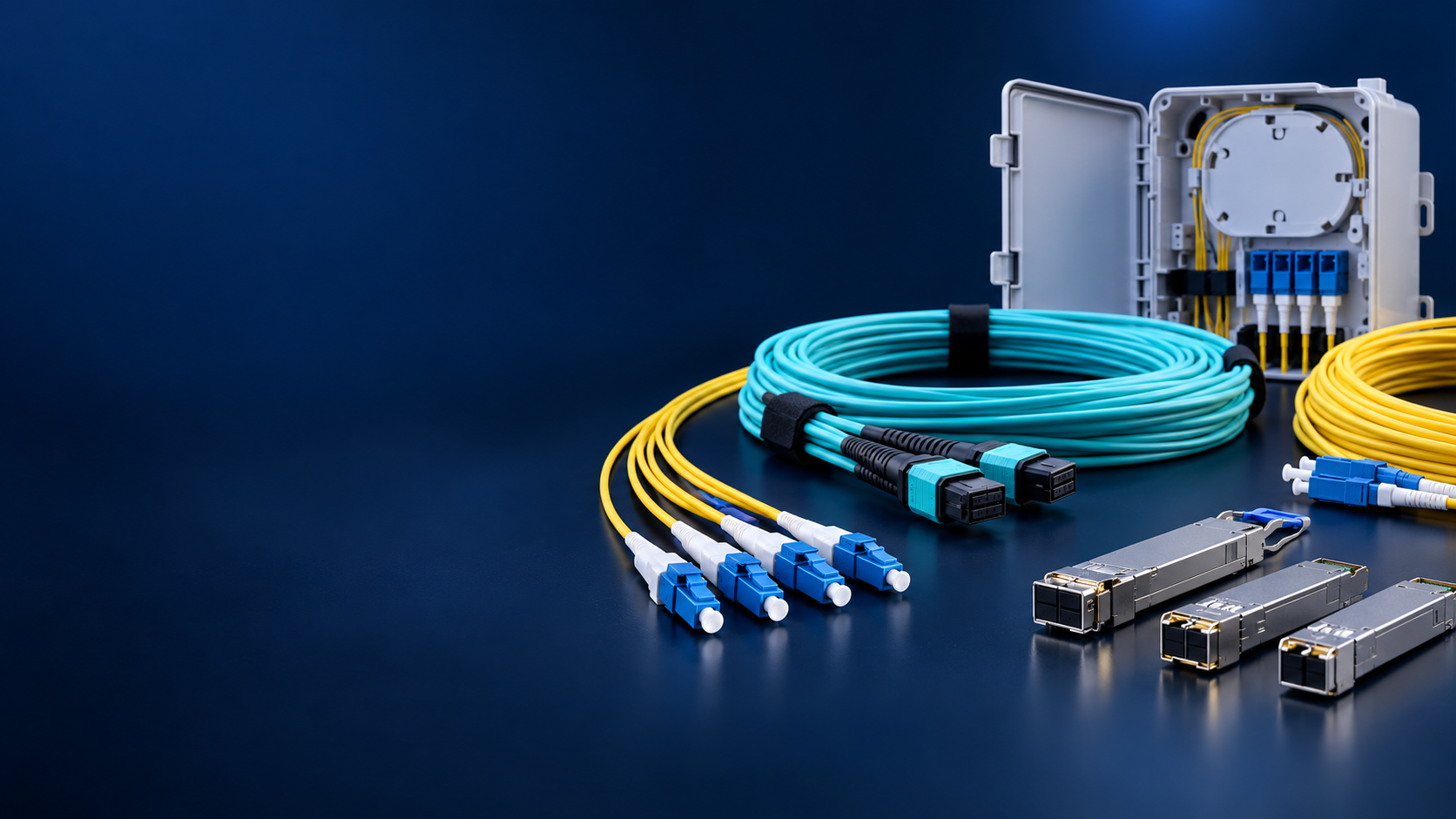
Plan 400G and 800G data center fiber cabling by starting with the optical interface, lane map, fiber type, MPO polarity, pathway density and channel-loss budget.
1. Start with the optical interface and lane assignment
The first planning question is the optical interface used by the equipment and transceiver. A 400G or 800G label can describe different architectures, fiber counts and lane allocations. Confirm the applicable transceiver or optical-engine document, connector interface, fiber type, reach, wavelength plan and whether the link is parallel single-mode, parallel multimode or a breakout design.
Use the interface and lane map to define the trunk, patch cord, cassette or breakout. A passive MPO assembly carries the optical paths selected by the design; it does not perform protocol conversion, lane reshaping or speed conversion.
| Design input | Required decision |
|---|---|
| Optical interface | Connector family, fiber count and active positions at each endpoint |
| Fiber type | Single-mode OS2 or multimode OM4/OM5 according to the optics and reach |
| Lane map | Transmit, receive, lane order and any breakout mapping |
| Polarity | End-to-end position mapping including keys, pins, cassettes and adapters |
| Loss budget | Reference planes, wavelength, component loss and acceptance limit |
2. Select MPO-12 or MPO-16 from the equipment interface
MPO-12 and MPO-16 use different fiber-position counts and mechanical interfaces. Select the format required by the equipment, transceiver and mating components. Do not substitute an MPO-16 assembly for an MPO-12 assembly because both are described as high-density cabling, and do not assume all positions are active in every architecture.
The bill of materials should state fiber count, row arrangement where applicable, key orientation, pinned or unpinned status, polish, cable construction and the position map. If a link uses a breakout, show which positions connect to each duplex or parallel endpoint and identify unused positions.
- Confirm the equipment receptacle and mating connector pin status before ordering cords.
- Use the approved position drawing instead of relying on a Type A, B or C label alone.
- Check that APC, UPC, single-mode and multimode interfaces are not mixed in the proposed BOM.
- Record whether the design reserves dark fibers for growth, maintenance or a future migration.
3. Compare OS2 and OM4 by reach, optics and pathway plan
OS2 and OM4 serve different optical systems. OS2 is a single-mode category commonly used for longer reach and parallel single-mode architectures. OM4 is a multimode category used with compatible multimode optics for shorter data-center links. The correct choice follows the transceiver specification, reach and channel-loss budget rather than a preference for one cable color or connector format.
Pathway density and bend management also matter. High-density trunks, cassettes and breakout assemblies should maintain the required bend radius and provide clear labeling at both ends. In a migration design, leave enough pathway and rack space for the selected future interface instead of mixing incompatible assemblies today.
| Question | Why it matters |
|---|---|
| What fiber does the optical module require? | A cable category cannot make an incompatible optic work. |
| What is the complete channel length? | Reach and loss limits must include every connector and patch point. |
| How many active lanes are used? | The trunk and breakout must expose the required positions. |
| How dense is the pathway? | Cable diameter, bend radius and labeling affect installation and service. |
| Will the design migrate later? | Reserved positions and rack space should follow a documented roadmap. |
4. Validate polarity, cleanliness and insertion loss
A high-speed cabling design is complete only when the end-to-end mapping is testable. Create a worksheet from the first equipment port through the equipment cord, adapter, trunk, cassette or breakout and the remote equipment port. Validate transmit-to-receive direction and every active position.
Inspect and clean both mating interfaces before testing. Then measure continuity and position mapping, followed by insertion loss using the project reference method, wavelength and limit. For multimode links, record the launch condition. Retain per-lane results and the drawing revision so a failed lane can be isolated without changing polarity during troubleshooting.
Engineering note: The phrase 800G cabling describes a cabling application. It should not be used as evidence that an 800G optical transceiver SKU is available in the product catalog.
5. Build a procurement-ready bill of materials
A procurement request should include endpoint equipment and port identifiers, optical module or interface document, fiber type, trunk length, connector format, pin status, polish, polarity, breakout ratio, labels, bend-radius requirements, test reports and packaging. Ask the supplier to flag any assumption before quoting.
When a project is still in the architecture stage, request a configuration review rather than a generic 400G or 800G cable. The review should return an annotated BOM, a lane and polarity map, expected loss budget and a list of information still required from the active equipment supplier.
- Approve one controlled drawing for the complete channel.
- Use exact connector and fiber terminology in the purchase order.
- Require per-assembly identification and test records.
- Define substitutions and migration options before production starts.
Procurement FAQ
Q: Does a 400G link always use MPO? A: No. The selected optical implementation may use an MPO parallel interface, a breakout assembly or duplex LC for a wavelength-multiplexed design. Confirm the module document first.
Q: Can an MPO-16 trunk replace an MPO-12 trunk? A: No. Fiber count, ferrule interface, active positions, keying, pin status and polarity must all match the mating equipment and channel map.
Q: What must be tested before handover? A: Inspect and clean interfaces, verify continuity and polarity, then measure per-lane insertion loss at the specified wavelength and reference plane; retain the map and raw results.
Related Fibtele product categories
Final specifications, standards, compatibility, MOQ and lead time must be confirmed for the selected model before ordering.
Primary references
- Cisco 400G QSFP-DD Cable and Transceiver Modules Data Sheet — Cisco
- Cisco OSFP 800G Transceiver Modules Data Sheet — Cisco
- IEC 61280-4-1:2019+AMD1:2021 — Installed multimode cabling plant attenuation measurement — International Electrotechnical Commission
- IEC 61280-4-2:2024 — Installed single-mode attenuation and optical return loss measurements — International Electrotechnical Commission
- IEC 61754-7-1:2014 — Type MPO connector family, one fibre row — International Electrotechnical Commission
- IEC 61754-7-2:2017 — Type MPO connector family, two fibre rows — International Electrotechnical Commission
- IEC TR 61282-15:2017 — Testing multi-fibre cable plant terminated with MPO connectors — International Electrotechnical Commission
- IEC 61300-3-35:2022 — Visual inspection of fiber-optic connector interfaces — International Electrotechnical Commission
- IEEE P802.3bs — 200 Gb/s and 400 Gb/s Ethernet Task Force — IEEE Standards Association
- IEEE P802.3cm — 400 Gb/s over Multimode Fiber Task Force — IEEE Standards Association
- IEEE P802.3df — 400 Gb/s and 800 Gb/s Ethernet Task Force — IEEE Standards Association
- ANSI/TIA-568.3-E — Optical Fiber Cabling and Components Standard announcement — Telecommunications Industry Association
Standards are revised over time. Check the current edition and the project specification before approving a design or purchase.