
MPO Polarity and Testing Guide: Methods A, B, C, Mapping, and Acceptance
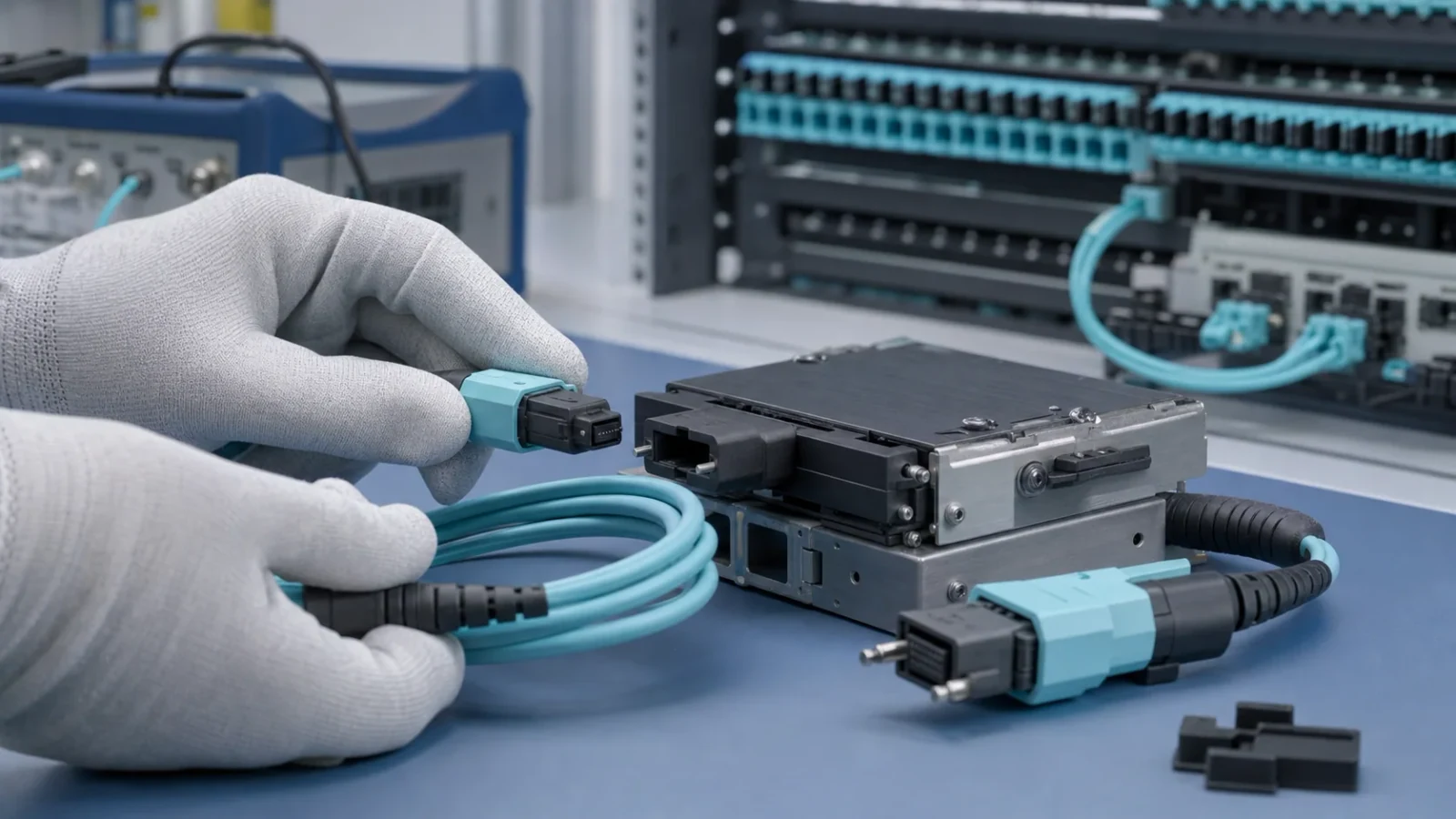
An engineering guide to MPO fiber-position mapping, guide pins, key orientation, end-to-end transmit/receive polarity, inspection, attenuation testing, and acceptance records.
1. Separate connector interface, cable mapping, and system polarity
MPO describes a multi-fiber push-on connector family. The connector interface, cable assembly, cassette or breakout, adapter orientation, and active equipment each contribute to the final channel. Polarity is correct only when every transmitter reaches its intended receiver and every receiver is connected to the intended transmitter.
The terms Type A, Type B, and Type C commonly describe array-cable fiber-position mappings used within structured-cabling polarity methods. They are useful building blocks, but they are not complete channel specifications. A designer must show the end-to-end position map across every component and define the reference view used for numbering.
Engineering note: MTP® is a US Conec brand for specific MPO-format products. Do not use “MTP” as a generic replacement for MPO or imply brand authorization without evidence.
2. Control the physical variables before discussing polarity
An MPO purchase description should state fiber count and active positions, the number of ferrule rows, single-mode or multimode fiber, polish where applicable, key orientation, pinned or unpinned interface, cable construction, and the required position map. Position numbering must be shown from a named viewing direction because drawings viewed from opposite ends appear mirrored.
Guide pins align the rectangular ferrules. A mating pair requires the specified pinned-to-unpinned relationship; two pinned interfaces interfere, while two unpinned interfaces lack the intended guide-pin alignment. Pin arrangement is independent of optical polarity, and words such as male and female should never replace a full map and interface drawing.
- Confirm whether the active equipment receptacle is pinned or unpinned before ordering the equipment cord.
- Do not mate APC and non-angled interfaces or mix incompatible keying and polish configurations.
- Identify unused positions and whether they contain fiber, are dark, or are reserved.
- For multi-row ferrules, use the applicable row and position numbering from the controlled interface specification.
3. Read Type A, B, and C as position mappings
The following table shows the common 12-position array-cable shorthand. It is intentionally limited to position mapping from one end of a cable assembly to the other. Adapter keys, cassettes, duplex patch cords, and transceiver lane assignments must still be added to the channel drawing.
| Cable mapping | Representative position map | Pattern | Design warning |
|---|---|---|---|
| Type A | 1→1, 2→2, …, 12→12 | Straight-through | The channel still needs a transmit/receive reversal elsewhere |
| Type B | 1→12, 2→11, …, 12→1 | Complete array reversal | Lane order and unused positions must match the active interface |
| Type C | 1→2, 2→1; 3→4, 4→3; … | Adjacent-pair swap | Intended for paired positions; verify cassette and duplex-pair mapping |
Engineering note: Some suppliers use labels inconsistently. Accept a position-to-position drawing as the controlling requirement, not a letter alone.
4. Build an end-to-end transmit/receive worksheet
Start at each equipment transmitter and follow its optical position through the equipment cord, adapter, trunk, cassette or breakout, duplex patching, and remote equipment interface. Record the position at every boundary. Repeat from the opposite direction and for every active lane. The worksheet should end with the intended receiver identifier, not merely another fiber number.
Parallel Ethernet interfaces can use only selected positions in a larger ferrule and may assign transmit and receive lanes to different position groups. Breakout applications map aggregate lanes to separate interfaces. Use the exact IEEE PHY and equipment documentation for that mapping; a cable suitable for one parallel interface is not automatically suitable for another with the same aggregate rate.
- Name both endpoints, ports, lanes, transmitters, and receivers.
- Show adapter key orientation and pinned or unpinned status at every MPO mating plane.
- Show cassette or fan-out mapping rather than treating it as an opaque box.
- Preserve one approved drawing revision for installation, testing, and future moves or changes.
5. Inspect and clean the entire array
A single contaminated fiber can fail one lane while the remaining lanes appear healthy. Inspect both mating interfaces with equipment appropriate for multi-fiber ferrules, clean using a method approved for the connector, and reinspect before mating. Dust caps limit exposure but are not evidence that an end face is clean.
IEC 61300-3-35 defines visual inspection procedures for fiber-optic connector interfaces. Inspection addresses visible contamination, scratches, and defects; it does not replace attenuation, return-loss, continuity, or geometry measurements. Store images with the connector side, position orientation, serial or cable identifier, date, and disposition when images form part of acceptance.
- Use a probe and tip that can view the full ferrule and resolve individual fiber positions.
- Clean both sides of an adapter; mating a clean connector to a dirty one can contaminate both.
- Protect accepted interfaces immediately and limit unnecessary mating cycles.
- Investigate recurring contamination as a handling or packaging process issue.
6. Test mapping first, then optical performance
Begin with continuity and position mapping. A visible source or automated polarity tester can identify gross mapping errors, but the test setup and viewing safety procedure must be controlled. Compare the measured map with the approved end-to-end worksheet for all active and reserved positions.
Measure insertion loss for each required channel using the reference method, launch condition, wavelength, and acceptance limit defined by the project or applicable standard. For multimode links, launch condition can materially affect the result. Measure return loss, ferrule geometry, or other parameters when the controlled product or channel specification requires them. One passing aggregate value must not hide a failed lane.
Engineering note: Never look into a fiber or connector to check continuity. Verify that the path is de-energized or use suitable instruments and optical-safety procedures.
7. Distinguish component tests from installed-channel tests
A factory cable-assembly test can verify its own position map and optical performance with defined reference interfaces. An installed-channel test includes the field adapters, trunks, cassettes, patch cords, and equipment cords in the selected reference plane. State the reference planes so connectors are neither omitted nor counted twice.
When a channel fails, compare position mapping first, then inspect, clean, and retest before replacing components. If loss remains high, test logical sections to isolate a trunk, cassette, connector, or bend. Preserve original failures and final retest results; overwriting a failure removes useful evidence about installation quality and recurring defects.
8. Release only with a complete MPO acceptance record
The acceptance record should be detailed enough for a technician who did not install the channel to reproduce the test and replace one component without changing polarity.
| Control | Record before installation | Acceptance evidence |
|---|---|---|
| Interface | MPO variant, fiber/row count, keying, polish and pin status | Physical inspection against controlled drawing |
| Mapping | Position map for every cord, trunk, cassette and breakout | Measured continuity and position map |
| Active lanes | PHY, Tx/Rx lane identifiers and unused positions | Every transmitter reaches its intended receiver |
| Cleanliness | Inspection method and acceptance criteria | Inspect-clean-inspect result for both mating sides |
| Insertion loss | Reference planes, method, wavelength, launch and limit | Per-channel measured value and pass/fail |
| Other optical tests | Return loss or geometry when specified | Per-channel or per-ferrule results |
| Traceability | Assembly identifiers, drawing revision and test equipment | Signed record with raw files and retest history |
| Change control | Allowed substitutions and polarity owner | Updated map and retest after any component change |
Related Fibtele product categories
Final specifications, standards, compatibility, MOQ and lead time must be confirmed for the selected model before ordering.
Primary references
- IEC 61754-7-1:2014 — Type MPO connector family, one fiber row — International Electrotechnical Commission
- IEC 61300-3-35:2022 — Visual inspection of fiber-optic connector interfaces — International Electrotechnical Commission
- IEC 61300-3-4:2023 — Attenuation measurement — International Electrotechnical Commission
- ANSI/TIA-568.3-E — Optical Fiber Cabling and Components Standard announcement — Telecommunications Industry Association
- US Conec FAQ — MTP® connector and generic MPO interfaces — US Conec
Standards are revised over time. Check the current edition and the project specification before approving a design or purchase.