
OTDR vs OLTS: Which Fiber Test Should You Use?
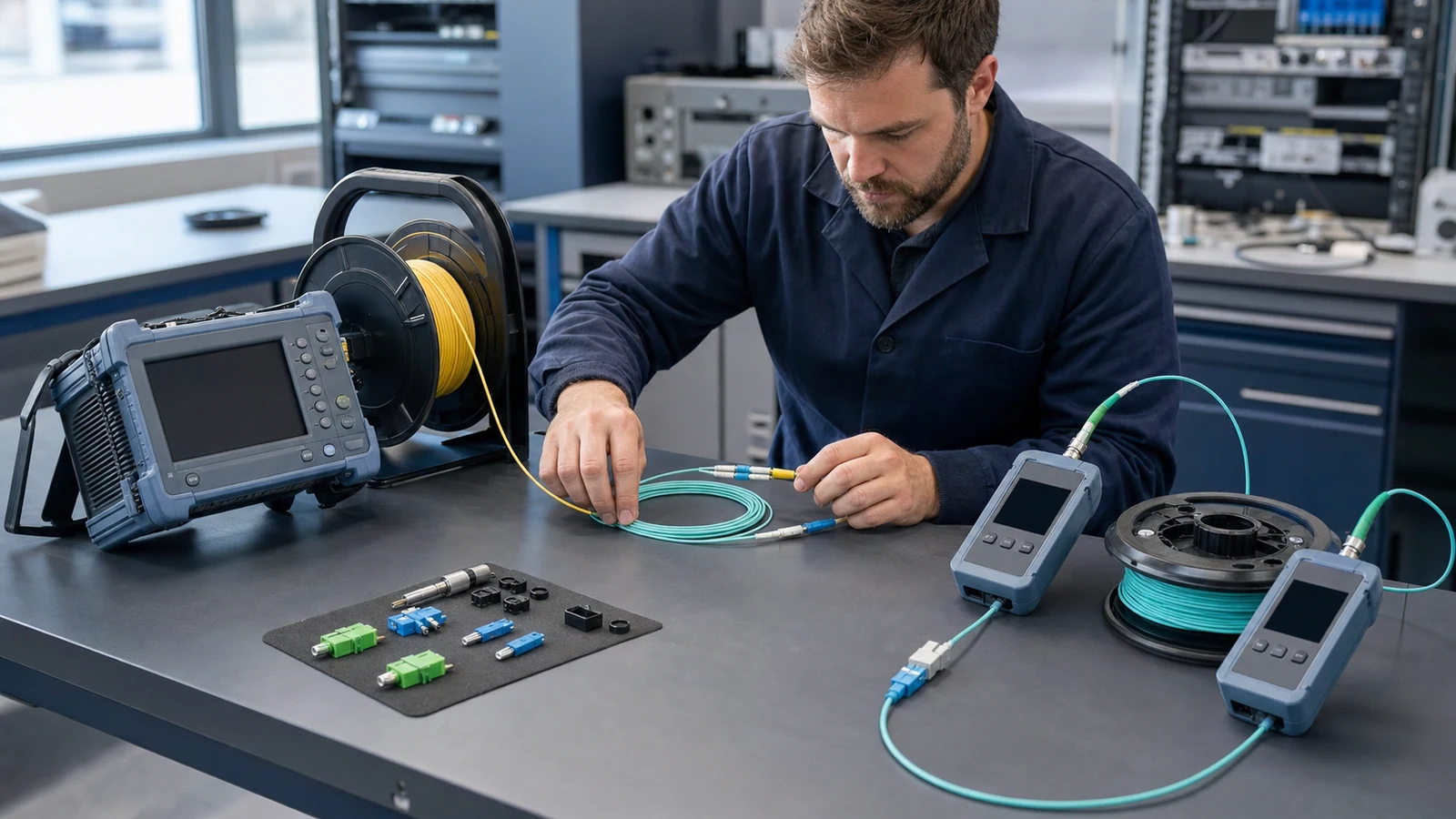
OTDR and OLTS measurements answer different questions. This guide explains when to use each method and how to build a defensible fibre acceptance workflow.
1. Start with the acceptance question, not the instrument
Choose a test by defining the evidence the owner needs. If the question is whether the complete installed path meets an end-to-end attenuation limit, an optical loss test set is the direct tool. If the question is where a splice, bend, connector, or break is located, an optical time-domain reflectometer provides spatial information.
A contract may require both results, a specific method, or testing in both directions. The applicable cabling standard, network-owner specification, fibre type, topology, and link length take precedence over an instrument vendor's default limit.
2. What an OLTS measures
An OLTS combines a stabilized optical source and optical power meter. After a reference is established with defined test reference cords, the cable plant is inserted into the measurement path. The difference between reference power and received power is reported as end-to-end insertion loss.
This arrangement is analogous to normal link operation: light enters one end and the remaining power is measured at the other. The result includes the combined effects of fibre, mated connections, splices, and passive components between the selected reference planes.
- Use test wavelengths appropriate to the installed fibre and intended application.
- Document whether a one-, two-, or three-cord reference method was used because the reference planes affect the result.
- For multimode testing, control launch conditions as required by the applicable standard.
3. What an OTDR measures
An OTDR launches optical pulses and measures light returned by Rayleigh backscatter and Fresnel reflections as a function of time. With the configured group index, it converts time into distance and displays a trace. Trace analysis can estimate fibre attenuation and the loss, reflectance, and position of individual events.
The measurement is indirect and depends on setup choices such as wavelength, pulse width, averaging time, range, resolution, event thresholds, and refractive index. Launch and receive fibres are normally used so that the first and last connections can be evaluated outside the instrument's dead zones.
Engineering note: A wider pulse can improve dynamic range but reduces spatial resolution and increases dead zones. Use the shortest pulse that still provides an adequate signal-to-noise ratio for the link under test.
4. OTDR and OLTS comparison
| Decision factor | OLTS / source and power meter | OTDR |
|---|---|---|
| Primary result | End-to-end insertion loss | Trace versus distance and event table |
| Fault location | Does not locate the cause | Locates reflective and non-reflective events within resolution limits |
| Access during test | Normally requires equipment at both ends | Main instrument operates from one end; a receive fibre is placed at the far end when end-connector characterization is required |
| Direction effects | Test direction can affect connector combinations and reporting | Event loss can differ by direction because backscatter coefficients differ; bidirectional averaging can improve splice-loss assessment |
| Key setup risks | Incorrect reference, dirty cords, unstable source, unsuitable multimode launch | Incorrect pulse/range/index, dead zones, poor launch/receive fibres, automated event misclassification |
| Best acceptance use | Proves total path attenuation against the channel limit | Documents construction quality and establishes a fault-location baseline |
5. Why the two results do not have to match exactly
An OLTS and an OTDR use different physical measurement principles and reference planes. The OLTS measures transmitted power directly across the whole path. The OTDR estimates loss from a backscatter trace and may exclude launch or receive connections if the reference fibres or cursors are configured differently.
A splice between fibres with different backscatter coefficients can appear as unusually high loss or even apparent gain in one direction. Testing from both ends and averaging the event loss reduces this directional backscatter effect. It does not turn the OTDR result into an OLTS measurement; the end-to-end acceptance result should still be interpreted under its specified method.
6. A practical two-tier acceptance workflow
First inspect and clean every test and link connector. Verify test reference cords, allow sources to stabilize, set the prescribed wavelengths, and establish the OLTS reference without disturbing it. Test every required fibre and direction, then compare measured insertion loss with the approved limit derived from the link design or standard.
Next connect suitable OTDR launch and receive fibres. Acquire traces at the specified wavelengths and directions using settings appropriate to link length and expected loss. Review the trace manually rather than accepting every automatically generated event. Investigate any event that exceeds its limit, any unexpected reflector, and any section whose attenuation slope is abnormal.
- Resolve failed end-to-end loss before declaring the cable plant acceptable.
- Use OTDR evidence to isolate whether excess loss is distributed or concentrated at a specific event.
- After repair, repeat the affected OLTS test and OTDR trace under the same documented conditions.
7. Record enough information for another technician to repeat the test
A useful report includes cable and fibre identifiers, endpoints, fibre type, test direction, wavelength, reference method, acceptance limit, measured loss, instrument model and serial number, calibration status, and test-cord identifiers. OTDR records additionally need pulse width, range, averaging, index setting, launch/receive fibre lengths, event thresholds, and the original trace file.
Store native instrument files as well as PDFs or summary tables. Native traces allow later re-analysis with changed event thresholds and provide a baseline for comparing ageing, construction damage, or a future cable break.
Related Fibtele product categories
Final specifications, standards, compatibility, MOQ and lead time must be confirmed for the selected model before ordering.
Primary references
- IEC 61280-4-2:2024: Single-mode attenuation and optical return loss measurements — International Electrotechnical Commission
- IEC 61280-4-1:2019: Multimode installed cabling attenuation measurement — International Electrotechnical Commission
- ISO/IEC 14763-3:2024: Testing of optical fibre cabling — International Organization for Standardization
- IEC 61746-1:2009: Calibration of OTDRs for single-mode fibres — International Electrotechnical Commission
Standards are revised over time. Check the current edition and the project specification before approving a design or purchase.