
How to Calculate a Fiber-Optic Link Loss Budget
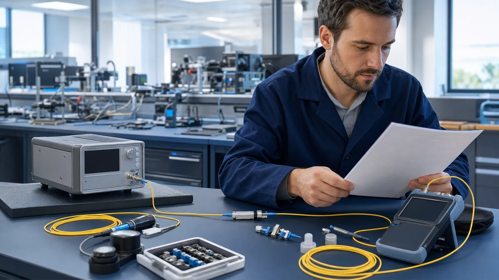
A practical method for converting transmitter, receiver, fibre, connector, splice, and passive-component data into a defensible optical loss budget.
1. Separate the active power budget from the passive loss estimate
The active optical power budget and the passive link loss are related but different quantities. The active budget is derived from the transceiver limits: minimum launch power minus the receiver sensitivity associated with the required data rate, reach class, and error-performance target. The passive estimate predicts how much of that budget the installed path will consume.
A design passes the maximum-loss check when the estimated worst-case channel loss does not exceed the available active budget. It must also pass a minimum-loss or receiver-overload check: on a very short path, maximum transmitter output minus minimum channel loss must not exceed the receiver maximum input level.
Engineering note: Use guaranteed limits from the exact transceiver or system specification. Typical optical power values are not acceptance limits.
2. Build a physical inventory before doing arithmetic
Draw the complete optical path from transmit interface to receive interface. Record fibre type and route length, every mated connector pair, every planned splice, and every passive element such as a splitter, WDM, attenuator, monitoring tap, or coexistence filter. State which equipment connectors are included so that the same interface is not counted twice.
Create a separate worksheet for each direction and wavelength. Fibre attenuation, WDM passband loss, splitter performance, and transceiver power can all vary with wavelength. Bidirectional links therefore cannot safely be represented by one generic number.
- Use installed route length, including service loops, rather than straight-line map distance.
- Use maximum specified component loss over the required temperature and wavelength range when designing a worst-case budget.
- Keep design assumptions, measured results, and manufacturer limits in separate columns.
3. Apply the loss equation consistently
For a simple point-to-point path, estimated channel loss can be written as: fibre length multiplied by the design attenuation coefficient, plus connector count multiplied by connector-pair loss, plus splice count multiplied by splice loss, plus the specified insertion loss of all other passive devices, plus engineering margin.
The connector count means mated optical connections in the defined channel, not individual connector plugs. A duplex link contains two separate optical fibres; calculate each fibre path rather than doubling the loss merely because the interface is duplex.
Engineering note: All terms are expressed in decibels, so they are added. Do not add optical powers expressed in dBm as though they were losses in dB.
4. Worked example: a 10 km single-mode path
The following is an illustrative calculation, not a universal acceptance limit. Replace every design value with the applicable cable, connector, splice, passive-device, and project specification. The example assumes a 1550 nm point-to-point path with no splitter or WDM in the channel.
If the applicable transmitter minimum is -3 dBm and the receiver sensitivity is -20 dBm, the available active budget is 17 dB. Subtracting the illustrative 9.10 dB design loss leaves 7.90 dB of residual budget. The calculation is incomplete until receiver overload, dispersion, reflectance, and any system-specific penalties are also checked.
| Loss element | Quantity | Illustrative design value | Calculated loss |
|---|---|---|---|
| Single-mode cable at 1550 nm | 10 km | 0.35 dB/km | 3.50 dB |
| Mated connector pairs | 4 | 0.50 dB per pair | 2.00 dB |
| Fusion splices | 6 | 0.10 dB per splice | 0.60 dB |
| Other passive devices | None | Use specified worst-case loss | 0.00 dB |
| Engineering margin | 1 | Project-defined | 3.00 dB |
| Estimated design loss | — | Sum of all rows | 9.10 dB |
5. Choose margin deliberately rather than hiding uncertainty
Engineering margin is capacity reserved for effects not already covered by component limits. It may account for future repair splices, additional patching, ageing, temperature variation, measurement uncertainty, and controlled network growth. A margin should have an owner and a stated purpose; otherwise different reviewers may unknowingly reserve the same allowance twice.
Worst-case component limits can already include environmental and manufacturing variation. When they do, adding another blanket allowance for the same variation is unnecessary conservatism. Conversely, a budget based on typical laboratory values needs more protection and is rarely suitable for contractual acceptance.
6. Treat splitters, WDM systems, and PONs as wavelength-dependent paths
For a splitter, include the specified insertion loss from the selected input port to the selected output port; theoretical splitting loss alone does not include excess loss or port variation. Cascaded splitters are evaluated as cascaded devices, including connectors and splices between stages.
For CWDM or DWDM, add the insertion loss of each multiplexer, demultiplexer, OADM, coexistence filter, and other element traversed by that channel. For a PON, compare each upstream and downstream optical distribution path with the optical path loss class of the actual OLT and ONU interfaces. A nominal split ratio does not by itself prove compliance.
7. Turn the calculation into an acceptance record
Before commissioning, measure end-to-end attenuation at the specified wavelengths using the reference method required by the project or applicable standard. Compare measured insertion loss with the acceptance limit, not merely with another instrument reading. Record reference-cord method, test wavelength, direction, equipment identification, calibration status, and measurement uncertainty.
Use OTDR traces as complementary evidence to locate splices, connectors, macrobends, breaks, and unexpected reflective events. An OTDR event table and an end-to-end OLTS result answer different questions; keeping both provides a stronger baseline for maintenance and later fault isolation.
- Clean and inspect connector end faces before setting a reference or testing.
- Save both raw measurement files and the approved summary report.
- Recalculate the budget whenever the route, passive devices, wavelength plan, or transceiver class changes.
Related Fibtele product categories
Final specifications, standards, compatibility, MOQ and lead time must be confirmed for the selected model before ordering.
Primary references
- ITU-T G.652: Characteristics of a single-mode optical fibre and cable — International Telecommunication Union
- IEC 61280-4-2:2024: Single-mode attenuation and optical return loss measurements — International Electrotechnical Commission
- IEC 61280-4-1:2019: Multimode installed cabling attenuation measurement — International Electrotechnical Commission
- FOA Reference Guide: Fiber Optic Network Design — The Fiber Optic Association
Standards are revised over time. Check the current edition and the project specification before approving a design or purchase.