
PLC vs FBT Splitters: An Engineering Selection Guide
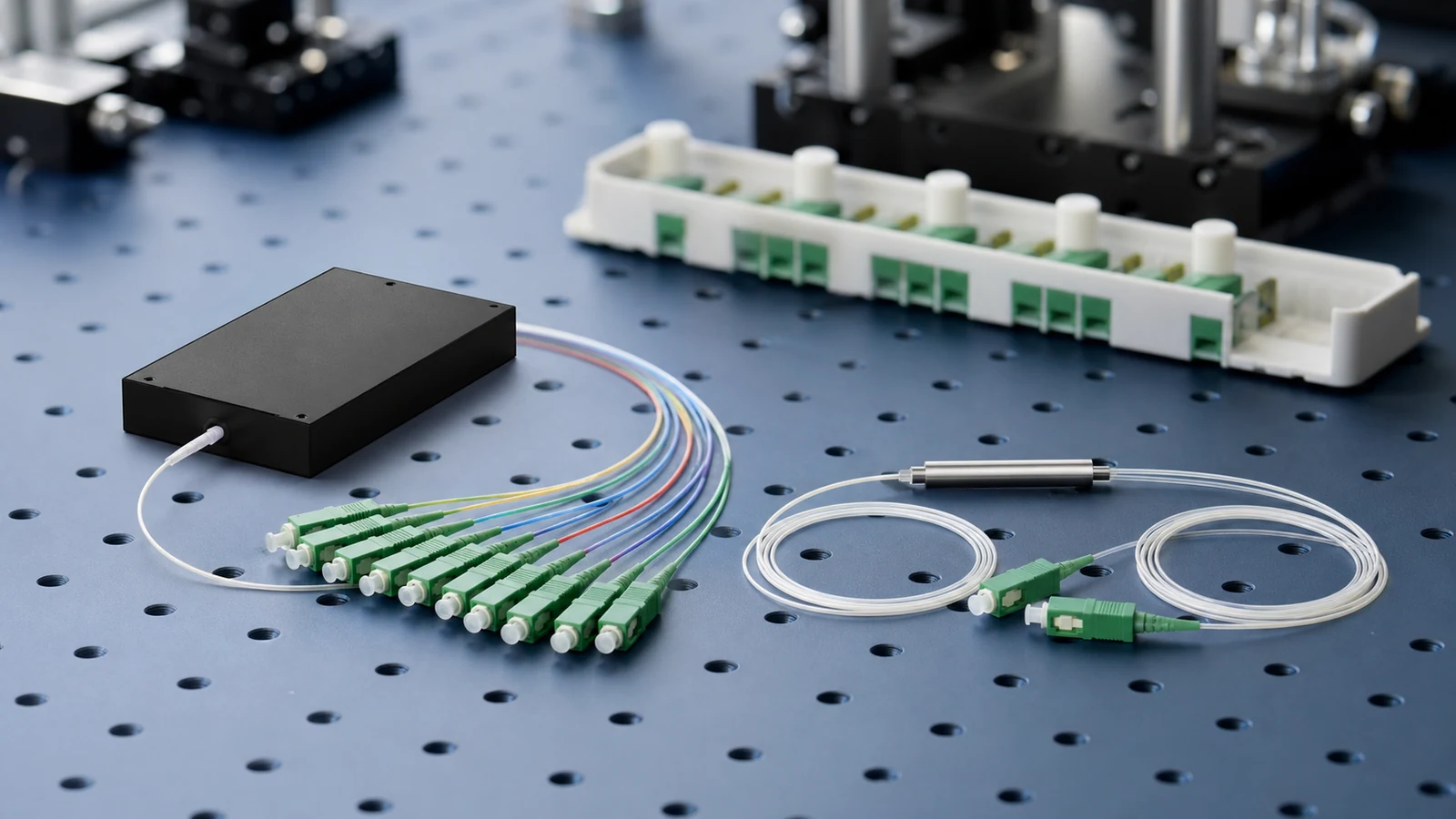
Select a PLC or FBT splitter by optical requirements, not by technology labels alone. Compare split ratio, port count, wavelength range, uniformity, loss, environment, and test evidence.
1. Define the splitter as an optical branching function
A passive optical splitter shares optical power among multiple fibre ports without optoelectronic conversion. International standards generally describe these products as non-wavelength-selective branching devices and specify optical, mechanical, environmental, and performance requirements. PLC and FBT describe manufacturing approaches; neither label by itself guarantees a performance class.
Write the required transfer function before selecting a technology. State input and output count, whether operation is bidirectional, balanced or asymmetric power ratio, operating wavelengths, connector or pigtail interfaces, package, fibre type, and environment.
2. How PLC and FBT devices are commonly implemented
A planar lightwave circuit splitter forms branching waveguides on a planar substrate and couples the circuit to input and output fibres. This approach is widely used for repeatable balanced 1 × N and 2 × N distribution with multiple output ports.
A fused biconical taper device is made by bringing fibres together, fusing them, and tapering the coupling region while monitoring transferred power. It is commonly used for 1 × 2 and low-port-count couplers, including deliberately asymmetric power ratios. Multiple stages can be cascaded, but every stage adds loss and tolerance that must be budgeted.
Engineering note: These are common implementation patterns, not procurement guarantees. Accept or reject the actual device against specified optical and environmental limits.
3. Compare the engineering decision factors
| Decision factor | PLC tendency | FBT tendency | What to specify |
|---|---|---|---|
| Split function | Often balanced 1 × N or 2 × N | Often 1 × 2 balanced or asymmetric coupling | Exact port count and power ratio at each output |
| Port scaling | Well suited to integrated multi-output circuits | Higher counts may use cascaded coupling stages | Maximum insertion loss and uniformity for the complete assembly |
| Wavelength behaviour | Can be designed for broad application bands | Coupling ratio can be more wavelength dependent | Limits at every operating and monitoring wavelength |
| Uniformity | Common choice when closely matched balanced outputs are required | Depends on coupling target and any cascade | Maximum output-to-output loss spread |
| Asymmetric taps | Possible with a purpose-designed circuit | Common commercial option for low-port-count unequal ratios | Nominal ratio plus tolerance over wavelength and temperature |
| Package and deployment | Bare fibre, blockless, module, tray, rack, and other assemblies | Tube or module formats are common | Dimensions, bend control, connector grade, sealing, and environmental category |
4. Calculate splitting loss without confusing it with insertion loss
For an ideal balanced N-way split, the physics-only division is 10 × log10(N) dB from the input to each output. That gives approximately 3.01 dB for 1 × 2, 6.02 dB for 1 × 4, 9.03 dB for 1 × 8, and 12.04 dB for 1 × 16. A real splitter has additional excess loss and port variation, so these values are not acceptance limits.
For an asymmetric output receiving fraction f of the input power, the ideal division is -10 × log10(f) dB. The complementary output has a different ideal loss. Use the manufacturer's guaranteed insertion-loss limits, including ratio tolerance and wavelength range, for the actual optical budget.
Engineering note: Connector loss, splice loss, and any enclosure or patching interfaces outside the splitter assembly must be counted separately unless the product limit explicitly includes them.
5. Wavelength and environment can reverse an apparently easy choice
List every service wavelength, coexistence wavelength, monitoring wavelength, and required direction. Compare insertion loss, ratio tolerance, return loss, directivity, polarization-dependent loss, and uniformity across that full range. A device that meets a target at one wavelength may not meet it elsewhere.
Also match the performance category to the real location. Controlled indoor cabinets, outdoor closures, aerial plant, and temperature-cycling environments impose different stresses. Review fibre proof strength, pigtail construction, connector end-face specification, sealing, vibration, mechanical retention, and qualification evidence—not only the room-temperature optical table.
6. Use the network loss class to constrain split ratio and cascade
In a passive optical network, the allowable optical path loss is set by the specific OLT and ONU interface class and applicable system specification. Splitter loss is usually the largest single passive term, but fibre, connectors, splices, coexistence elements, and engineering margin consume the same budget.
Evaluate the longest and shortest branches. The longest branch must remain within receiver sensitivity after worst-case loss; the shortest branch must also satisfy minimum path loss and receiver overload constraints. For cascaded splitting, calculate every end-to-end branch because stage ratios and feeder/distribution lengths can differ.
7. Procurement and incoming-test checklist
Choose PLC or FBT only after these requirements are fixed. For balanced multi-output distribution, a PLC implementation is often the straightforward candidate. For a low-port-count unequal tap, an FBT implementation may be efficient. If both qualified products meet the specification, compare complete installed cost, availability, package fit, field handling, and the supplier's traceable test evidence.
- Define the full port map, connector or pigtail type, fibre category, polarity, package, and labelling.
- Set maximum insertion loss per path, uniformity, ratio tolerance, return loss, directivity, and polarization-dependent loss where applicable.
- State all test wavelengths, directions, temperature range, environmental category, and qualification standard.
- Require measured port data or a test report tied to the device serial or lot identification.
- Inspect and clean connectors, then measure every required input-to-output path with the agreed reference method.
Related Fibtele product categories
Final specifications, standards, compatibility, MOQ and lead time must be confirmed for the selected model before ordering.
Primary references
- IEC 60875-1:2024: Non-wavelength-selective fibre optic branching devices — International Electrotechnical Commission
- IEC 61753-031-2:2014: Performance standard for single-mode 1 × N and 2 × N branching devices — International Electrotechnical Commission
- ITU-T G.671: Transmission characteristics of optical components and subsystems — International Telecommunication Union
- ITU-T G.984.2: GPON physical media dependent layer specification — International Telecommunication Union
Standards are revised over time. Check the current edition and the project specification before approving a design or purchase.