
FTTH Drop Cable and ITU-T G.657 Fiber Selection Guide
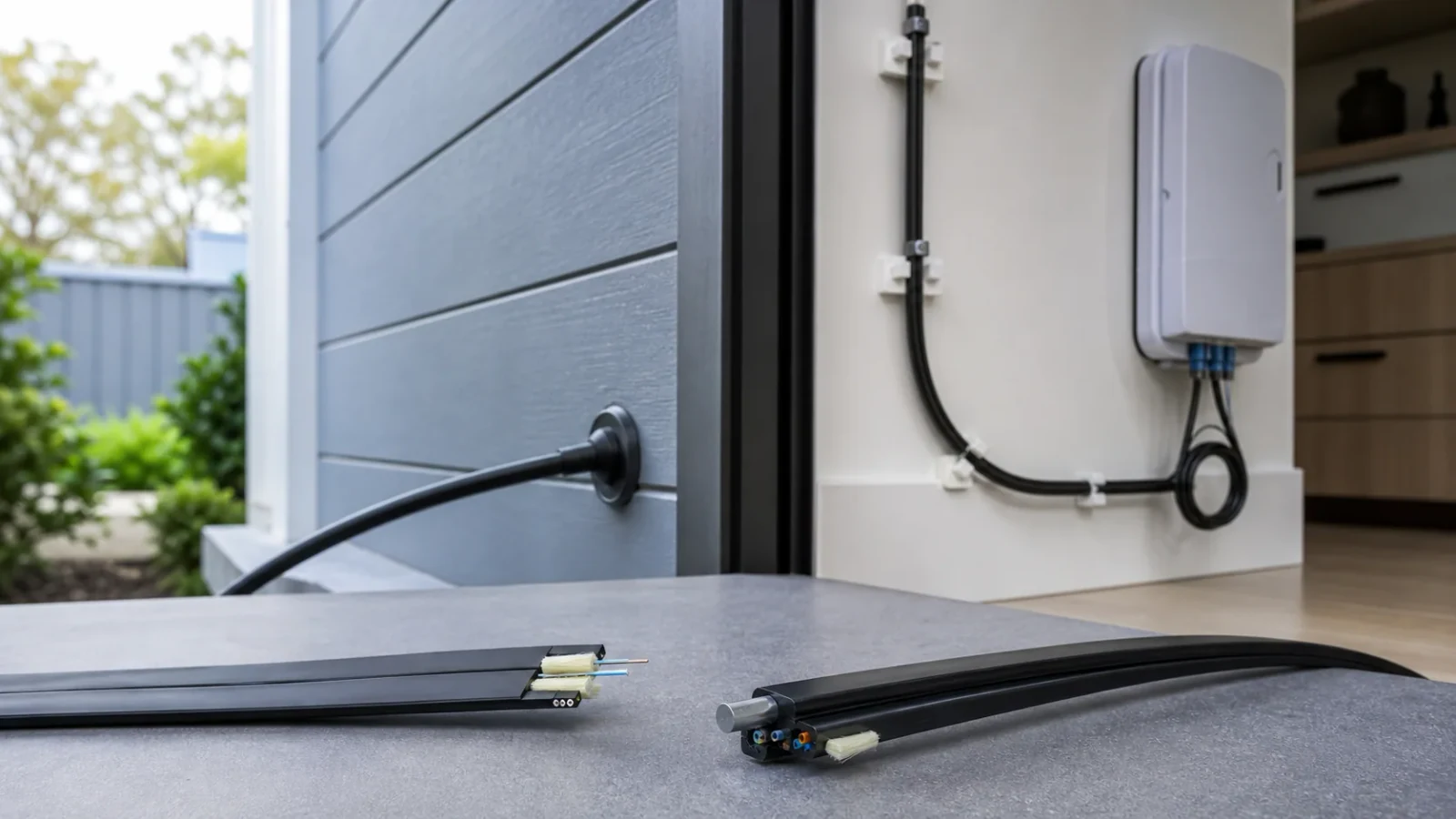
A practical guide to choosing G.657.A1, G.657.A2, or G.657.B3 fiber together with the correct indoor, outdoor, aerial, and self-supporting drop-cable construction.
1. Choose the fiber category and cable construction separately
ITU-T G.657 describes bend-improved single-mode fiber and cable transmission attributes. An FTTH drop cable is a complete mechanical product that also includes strength members, buffer or coating arrangement, sheath material, and possibly a messenger, armor, water-blocking elements, or access features. Selecting “G.657” alone therefore leaves most installation risks undefined.
Begin with the optical route and the physical route. The optical design sets wavelength, path-loss, reflectance, splice, and compatibility needs. The physical design sets pull method, span, support hardware, duct or wall routing, fire zone, UV and moisture exposure, temperature, bend locations, handling, repair access, and local regulatory requirements.
Engineering note: A fiber minimum design radius is not permission to bend a finished cable to that radius. The cable manufacturer’s installation and operating bend limits govern the cable.
2. Compare the current G.657 categories
The 2024 edition of ITU-T G.657 contains two Category A subcategories and one Category B subcategory. The earlier B2 category was merged into A2 in this edition, so new specifications should use current terminology while preserving legacy records where needed.
| Fiber category | Minimum design radius | Relationship to G.652.D | Planning use |
|---|---|---|---|
| G.657.A1 | 10 mm | Subset of and compliant with G.652.D | General access, transport, and space-limited routing where 10 mm design radius is sufficient |
| G.657.A2 | 7.5 mm | Subset of and compliant with G.652.D | Tighter access, indoor, cabinet, and high-density routing with a qualified cable design |
| G.657.B3 | 5 mm | Not necessarily G.652.D-compliant; system-compatible in access networks | Very tight, short-reach routing near the end of access networks or inside buildings |
Engineering note: ITU-T G.657 describes Category B for short-reach applications of less than 1,000 m near the end of access networks and for short indoor interconnections. Confirm the complete system design rather than extending B3 by assumption.
3. Survey every bend and installation constraint
Walk the intended route and record the smallest radius at trays, wall outlets, boxes, pole transitions, duct entries, corners, slack storage, and customer equipment. A route may meet its straight-line length target yet create high loss at one closure or behind one faceplate. Allow space for the actual cable diameter and installation tool, not only the bare fiber radius.
Separate the bend radius permitted while the cable is under installation tension from the smaller operating radius that may be allowed after release. Pulling around a tight corner combines bend and tensile stress. Staples, clips, cable ties, and closure hardware can also create microbending or crush even when the visible loop radius appears acceptable.
- Mark indoor, outdoor, buried, duct, facade, and aerial segments on the route drawing.
- Record maximum pulling length, bends between pull points, and access for future replacement.
- Define slack-storage location and loop diameter instead of leaving excess cable compressed in a box.
- Specify approved clamps and fastening force so hardware does not deform the cable.
4. Match cable construction to the environment
Indoor drop cable selection should address flame and smoke requirements, routing space, connectorization, and resistance to normal handling. Outdoor cable selection should address UV, water penetration, temperature, abrasion, and installation method. Aerial self-supporting or figure-eight designs additionally require a defined span, sag and tension design, messenger or strength-member arrangement, wind and ice assumptions where applicable, and compatible suspension or anchoring hardware.
Metallic strength members or armor can change grounding, bonding, lightning, and building-entry requirements. All-dielectric construction avoids an electrical conductor but still needs mechanical and environmental qualification. Local electrical, fire, building, and rights-of-way rules take precedence over a generic product description.
- Specify sheath material and required fire classification for each building zone.
- Define tensile, crush, impact, torsion, flexing, water, temperature, and UV evidence as applicable.
- State fiber count, cable dimensions, strength-member material, and stripping or access method.
- Use hardware qualified for the exact cable geometry and load case.
5. Check optical compatibility, splicing, and wavelengths
Category A fibers are designed to retain G.652.D compliance and can be specified where continuity with a G.652.D plant is important. Category B3 provides tighter bend performance but is not necessarily compliant with every G.652.D attribute. System compatibility does not mean that every mixed-fiber splice has identical loss under every splicer program and field condition.
Qualify the expected G.652.D-to-G.657 and G.657-to-G.657 splice combinations with the intended fusion splicer, cleaver, protection sleeve, and field process. Review mode-field-diameter information and perform bidirectional OTDR analysis where accurate splice-loss assessment is required, because apparent one-way gainer or exaggerated loss can result from backscatter differences.
Calculate the optical path at every operating and test wavelength. Macrobending effects are especially important at longer single-mode wavelengths, so a satisfactory measurement at one wavelength should not be assumed to cover all services or reveal every bend problem.
6. Write a complete drop-cable purchase specification
The request for quotation should bind the fiber category to a specific cable construction and test evidence. Values should come from the project design and applicable standards, not from copied catalogue language.
| Requirement group | Specify | Verify with |
|---|---|---|
| Optical fiber | Current G.657 subcategory, fiber count and applicable wavelengths | Controlled fiber and cable specification |
| Cable geometry | Construction, dimensions, mass, strength members and access method | Drawing and incoming dimensional check |
| Route | Indoor/outdoor/aerial/duct segments, length, bends and support points | Field survey and approved route drawing |
| Mechanical | Installation and operating bend limits, tensile, crush, impact and flex needs | Applicable IEC test evidence for the exact cable |
| Environmental | Temperature, water, UV and chemical exposure as applicable | Environmental test evidence and material specification |
| Safety and code | Flame, smoke, halogen, electrical and building-entry requirements | Current documents required by the destination and project |
| Termination | Connector or splice method, closure, clamp and slack management | Installation work instruction and sample qualification |
| Acceptance | Wavelengths, reference method, limits, OTDR baseline and records | Approved field test plan |
7. Qualify incoming cable before committing the route
On receipt, reconcile reel labels, cable marking, length, lot, construction, and fiber category with the purchase specification. Inspect for sheath damage, crushed flanges, poor winding, moisture exposure, or mixed identification. A generic compliance logo is not a substitute for a report or declaration tied to the exact cable configuration and applicable requirement.
For a new design or supplier, qualify a representative sample with the termination process, planned clamps, closures, and installation method. Review mechanical and environmental test evidence relevant to the route. Where the project depends on tight routing, perform an approved bend and optical-loss evaluation rather than demonstrating flexibility by manually wrapping an unidentified sample.
- Keep reel and lot identity linked to installed route sections.
- Confirm cable length before cutting and protect both ends from moisture and contamination.
- Record approved substitutions before installation.
- Retain reference samples when they support failure analysis or supplier comparison.
8. Test after installation and preserve an as-built baseline
After installation and termination, inspect and clean connector interfaces, verify continuity and polarity, and measure end-to-end attenuation at the project wavelengths using the defined reference method. Bidirectional OTDR traces can locate splices, connectors, unexpected bends, and damage and provide a baseline for later maintenance. Evaluate each fiber rather than assuming that one passing strand represents the cable.
Record route, reel and lot, endpoint identifiers, wavelength, direction, reference method, equipment and calibration status, raw files, results, exceptions, repairs, and final approval. Update the as-built drawing with actual splitter, splice, closure, and slack locations. If later work changes the bend path, closure packing, clamp, or wavelength plan, review the optical budget and retest the affected section.
Related Fibtele product categories
Final specifications, standards, compatibility, MOQ and lead time must be confirmed for the selected model before ordering.
Primary references
- ITU-T G.657 (08/2024) — Bend-insensitive single-mode optical fiber and cable — International Telecommunication Union
- ITU-T G.652 (08/2024) — Characteristics of a single-mode optical fiber and cable — International Telecommunication Union
- IEC 60794-1-21:2015+A1:2020 — Optical cable mechanical test methods — International Electrotechnical Commission
- IEC 60794-1-22:2017 — Optical cable environmental test methods — International Electrotechnical Commission
Standards are revised over time. Check the current edition and the project specification before approving a design or purchase.