
G.652 vs G.657 Single-Mode Fiber: Differences, Compatibility, and Selection
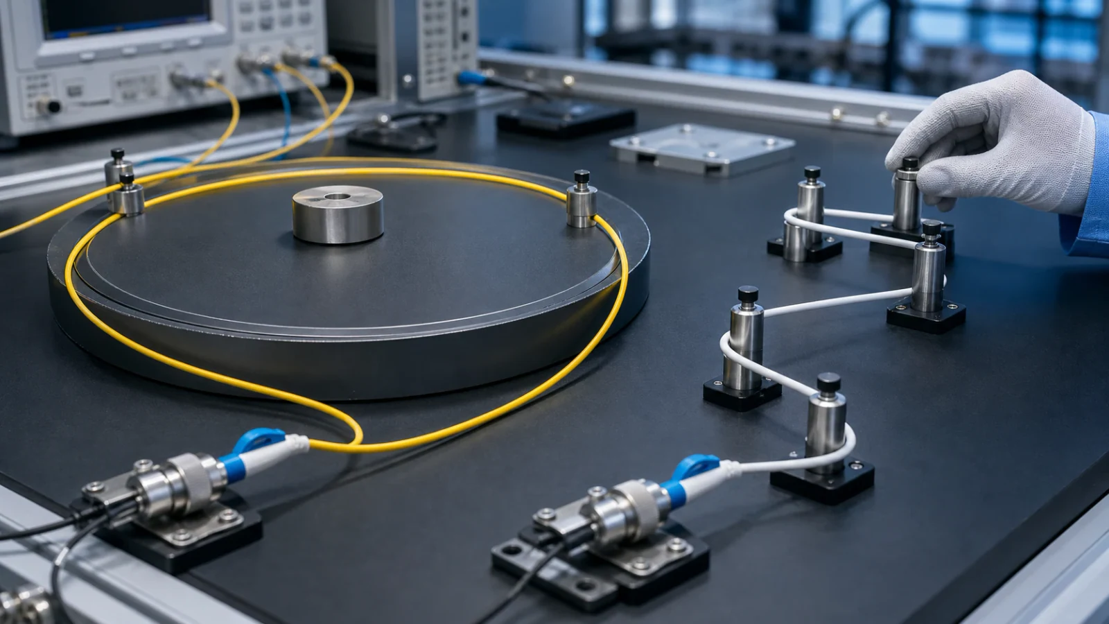
An engineering comparison of ITU-T G.652 and bend-insensitive G.657 single-mode fiber, including category compatibility, bend performance, deployment choices, splicing, testing, and procurement checks.
1. G.652 and G.657 describe fiber characteristics, not complete cable designs
ITU-T G.652 describes the geometrical, mechanical, and transmission attributes of a widely deployed single-mode optical fiber and cable whose zero-dispersion wavelength is near 1310 nm. G.652.D is commonly specified for general outside-plant, feeder, distribution, and transport applications.
ITU-T G.657 describes single-mode fibers designed for substantially improved macrobending performance. The Recommendation was developed for access networks and dense customer-premises routing, and its use has expanded to other space-constrained environments. Neither designation by itself defines jacket material, strength members, water blocking, crush resistance, fire rating, or a finished cable’s installation tension.
Engineering note: A procurement specification should name both the fiber category and the cable standard or detailed construction required for the installation environment.
2. Understand the G.657 category structure
The current G.657 framework separates category A and category B applications. Category A fibers are fully compliant with G.652.D and are intended for broad use across access, general transport, and data-centre networks where improved bending performance is useful. Subcategories A1 and A2 represent different macrobending performance requirements.
Category B targets very low bend-radius applications, particularly short reaches inside or near buildings and optical interconnections in constrained spaces. Category B is system-compatible with G.657.A and G.652.D in access networks, but it is not necessarily compliant with all G.652.D specifications. In the 2024 edition of G.657, the former B2 category was merged into A2, so procurement documents should use current terminology or clearly identify the intended edition.
- A1: bend-improved and G.652.D-compliant for broadly compatible deployment.
- A2: stronger bend performance while remaining in category A and G.652.D-compliant.
- B3: intended for the most demanding small-radius, short-reach access or interconnection use cases.
- Legacy category names on drawings should be reconciled with the current standard before ordering.
3. Why bending changes optical loss
When a single-mode fiber is bent, part of the guided optical field can radiate away from the core. The resulting macrobending loss depends on fiber design, bend radius, number of turns, wavelength, and cable construction. Longer wavelengths are often more sensitive to bending, so a link that appears acceptable at one wavelength can reveal a bend-related problem at another.
G.657 fibers use refractive-index designs that confine the optical field more effectively under tight bends. This reduces loss compared with conventional G.652 fiber under the prescribed bend tests, but it does not eliminate mechanical risks. Excessive bending can still stress glass, deform cable elements, create microbending, or violate the finished cable’s minimum bend radius.
- Use radius-control hardware rather than relying on installer judgement.
- Check both the installation bend limit and the smaller long-term operating bend limit when the cable datasheet distinguishes them.
- Avoid staples, cable ties, or closures that create local pressure and microbending.
- Test at the wavelengths required by the link specification and investigate wavelength-dependent excess loss.
4. Engineering comparison
The table is a selection guide, not a replacement for the value tables in the applicable Recommendation. Exact attenuation, dispersion, mode-field, proof, and macrobending requirements depend on the named subcategory and edition.
| Decision factor | G.652.D | G.657.A1 / A2 | G.657.B3 |
|---|---|---|---|
| Primary design goal | General-purpose single-mode transmission | G.652.D-compatible fiber with improved bend performance | Very strong bend performance for constrained short-reach use |
| Relationship to G.652 | Baseline family | Fully compliant with G.652.D | System-compatible in access networks but not necessarily G.652-compliant |
| Typical deployment emphasis | Feeder, distribution, outside plant, transport | Access, dense routing, indoor/outdoor distribution, data centres | Building entry, customer premises, compact modules and interconnections |
| Routing tolerance | Requires conventional bend management | More tolerant of tight routing than G.652 | Highest bend tolerance among the listed choices |
| Interworking | Widely installed and readily spliced | Designed for broad interoperability with G.652 | Can interwork in access systems; engineering qualification remains important |
| Procurement focus | Transmission attributes plus cable environment | Exact A subcategory plus cable environment | Confirm B3 application, reach, cable design, and compatibility |
5. Select fiber by network segment and route geometry
For long, well-managed feeder or transport routes, G.652.D remains a straightforward choice when the design does not require exceptional bend performance. For distribution frames, crowded closures, building risers, cabinets, indoor pathways, and data-centre routing, G.657.A can provide additional margin without giving up G.652 compliance.
G.657.B3 is best treated as an application-specific choice for short reaches where very small routing volumes are unavoidable. It should not automatically replace G.652 throughout a network. Confirm compatibility with splicing equipment, connectors, test procedures, and the system owner’s standard materials list.
- Map the smallest planned bend in trays, closures, boxes, wall outlets, and slack storage.
- Identify the operating and maintenance wavelengths, including monitoring wavelengths.
- Separate fiber choice from jacket, fire, UV, water, tensile, crush, and installation requirements.
- Standardise subcategories where possible to reduce field identification and inventory errors.
6. Splicing and connector compatibility
Fusion splicing G.652 to G.657 is common, especially between outside-plant distribution fiber and indoor drop fiber. The splicer should use a program suitable for the actual fibers, and the finished splice should be verified according to the link acceptance plan. Differences in mode-field diameter can affect true splice loss and the apparent loss reported by an OTDR.
A connector is specified by its own interface, geometry, and performance requirements; the fiber category alone does not determine connector quality. Control the fiber type, polish, ferrule geometry, cleanliness, and optical tests as a complete assembly. Avoid mixing unknown legacy fibers simply because all are labelled “single mode.”
7. Test mixed-fiber links carefully
An OTDR estimates event loss from backscatter. When two fibers have different backscatter characteristics or mode-field properties, the event may appear as a gain in one direction and an exaggerated loss in the other. Bidirectional measurement and averaging can provide a more representative splice-loss estimate when required by the test specification.
Use an optical loss test set for end-to-end attenuation acceptance when that is the governing method, and use the OTDR for event location, reflectance, continuity, and diagnostic information as specified. Maintain correct launch and receive fibers, connector polish, reference quality, and wavelength settings.
Engineering note: A low-loss OTDR trace does not prove that the cable is mechanically routed within its permitted bend radius. Installation inspection and cable-path records remain necessary.
8. Procurement and installation checklist
The most robust network often uses more than one fiber category: a general-purpose feeder, a G.652-compatible bend-improved distribution segment, and a highly bend-tolerant short drop where space is limited. The engineering task is to define each transition and verify it, rather than selecting one label for every environment.
- Name the current ITU-T category and subcategory, not only “single mode” or “bend-insensitive fiber.”
- State the required cable construction, environment, flame rating, strength, and installation method separately.
- Request the applicable fiber and cable data, including bend limits and attenuation specifications.
- Confirm splice-program support and test requirements for every planned fiber transition.
- Label reels, closures, trays, and drop assemblies so technicians can identify fiber category in service.
- Train installers that bend-improved fiber still requires controlled routing and mechanical protection.
Related Fibtele product categories
Final specifications, standards, compatibility, MOQ and lead time must be confirmed for the selected model before ordering.
Primary references
- ITU-T G.652 (08/2024) — Characteristics of a single-mode optical fibre and cable — International Telecommunication Union
- ITU-T G.657 (08/2024) — Characteristics of a bending-loss insensitive single-mode optical fibre and cable — International Telecommunication Union
- IEC 60793-2-50:2025 — Sectional specification for class B single-mode fibres — International Electrotechnical Commission
Standards are revised over time. Check the current edition and the project specification before approving a design or purchase.