
SFP Transceiver Selection Checklist: Form Factor, PHY, Fiber, Reach, and Diagnostics
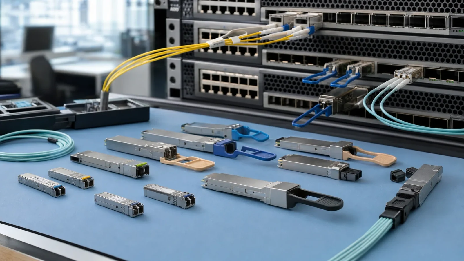
A standards-based checklist for selecting pluggable optical transceivers by host port, Ethernet PHY, fiber plant, optical budget, lane mapping, and management interface.
1. Define the service and PHY before choosing a module
A pluggable form factor describes a physical and electrical module family; it does not by itself specify an Ethernet reach, wavelength, connector, or optical power class. Begin with the host equipment model, slot or port identifier, supported port modes, target data rate, and the applicable IEEE 802.3 PHY or other transport specification.
Record whether the port operates as one serial lane, a four-lane aggregate, or a breakout. Also record any required forward-error-correction mode, auto-negotiation behaviour, clocking constraint, or transport framing. Two modules that both fit a cage may expose different electrical lane rates or require different host configuration.
- Identify both endpoints and confirm that they implement the same optical PHY.
- State whether the service is Ethernet, Fibre Channel, OTN, CPRI/eCPRI, or another protocol.
- Document the required line rate, lane count, duplex mode, and breakout mapping.
- Use the host vendor support policy as an input; do not infer support from form factor alone.
2. Use form-factor names as a filter, not as the final specification
The table below is an orientation guide for common product families. The listed applications are common uses, not guarantees for every module. The exact module specification and host documentation govern.
| Form factor | Electrical lane arrangement | Common Ethernet use | Still verify |
|---|---|---|---|
| SFP | One host lane | Lower-rate Ethernet services | PHY, coding, connector, wavelength, reach, diagnostics |
| SFP+ | One host lane | 10 Gigabit Ethernet services | Host interface, PHY, FEC if applicable, fiber and optical limits |
| SFP28 | One host lane | 25 Gigabit Ethernet services | Lane rate, FEC policy, fiber plant and optical budget |
| QSFP+ | Four host lanes | 40 Gigabit Ethernet or breakout | Aggregate versus breakout mode, per-lane mapping and connector |
| QSFP28 | Four host lanes | 100 Gigabit Ethernet or breakout | PHY, modulation, FEC, lane mapping and management revision |
Engineering note: Product names such as “10G” or “100G” are insufficient purchase descriptions. Include the standardized PHY or a fully controlled optical interface specification.
3. Match the installed fiber and optical interface
Confirm whether the path is single-mode fiber, multimode fiber, or a direct-attach or active optical cable assembly. For an installed optical path, record fiber category, route length, connector interfaces, patch panels, splices, splitters or WDM devices, and any coexistence filters. The route length must include service loops and patching rather than only map distance.
Duplex modules normally require the transmit wavelength and receive wavelength expected by the peer. Bidirectional modules use different transmit and receive wavelengths on one fiber and must be purchased as a complementary pair. CWDM and DWDM modules additionally require the correct channel plan and compatible passive filters. A wavelength label alone does not establish adequate power budget or dispersion performance.
- Match the module connector to the installed patching and polarity scheme.
- Verify the specified fiber category and modal bandwidth for multimode links.
- For parallel optics, verify fiber count, lane order, guide-pin arrangement, and end-to-end polarity.
- For single-fiber links, document the A-end and B-end wavelength pair explicitly.
4. Check maximum loss, minimum loss, and other reach limits
For the maximum-loss check, available optical budget equals the guaranteed minimum transmitter launch power minus the receiver sensitivity associated with the required performance target. Compare that budget with the worst-case channel loss at the relevant wavelength, including fiber attenuation, mated connectors, splices, passive devices, and a documented engineering margin.
Also perform a minimum-loss check. Maximum transmitter output minus the minimum expected path loss must remain below the receiver maximum input level. This prevents an otherwise healthy short link from overloading the receiver. Where the PHY defines dispersion, reflectance, transmitter-and-dispersion penalty, or other reach constraints, those checks remain necessary even when the simple dB budget passes.
Engineering note: Use guaranteed minimum and maximum values from the exact module specification. Typical power values and a marketing reach label are not acceptance limits.
5. Treat host interoperability as a system qualification
A module can conform to a mechanical or management agreement and still be rejected by host software, operate in the wrong port mode, or fail under traffic. Host platforms may check identification fields, supported applications, power class, firmware policy, temperature status, and vendor-specific data. Breakout and rate-select functions may also require explicit configuration.
Interoperability therefore has two parts: the module-to-host electrical and management relationship, and the end-to-end optical PHY relationship. Qualify both. If coding or reprogramming is permitted, record the programmed identity and checksum with the physical serial number so a later replacement can be reproduced and audited.
- Confirm cage type, allowed module power, cooling airflow, and operating-temperature requirement.
- Check host software version, port mode, supported FEC mode, and any approved-module policy.
- Verify link establishment, negotiated or configured rate, lane status, and sustained traffic.
- Test each intended host family rather than describing an untested module as universally compatible.
6. Use DOM or DDM as evidence, not as a substitute for testing
The SFF-8472 management interface defines identification and digital monitoring for SFP-class modules, while SFF-8636 defines a management interface used by QSFP-family modules. Depending on the module and implementation, reported values can include temperature, supply voltage, transmitter bias, transmit optical power, receive optical power, and warning or alarm thresholds.
Diagnostic thresholds are module-specific and must be read with the applicable management specification and module data. A receive-power value inside an alarm window does not prove sufficient engineering margin, low error rate, or correct polarity. Conversely, an alarm can result from configuration, calibration, contamination, or a real optical fault. Correlate diagnostics with an optical power measurement and error counters when troubleshooting.
- Capture module identification, date code, serial number, management revision, and calibration type.
- Record per-lane values for parallel modules rather than only an aggregate status.
- Compare readings after thermal stabilization and under representative traffic.
- Retain raw host output where permitted, but do not fabricate command output or thresholds.
7. Put the full requirement into the request for quotation
A controlled request prevents a supplier from having to infer the intended optical interface. Fill every row that applies and mark genuinely irrelevant fields as not applicable rather than leaving them ambiguous.
| Field | Required information | Acceptance evidence |
|---|---|---|
| Host | Vendor, platform, line card, port, software and port mode | Qualification record for that configuration |
| Service | Protocol, data rate, standardized PHY and FEC mode | Link and traffic test at required settings |
| Module | Form factor, lane count, power class and temperature range | Identification and environmental specification |
| Optical path | Fiber category, length, connector, splices and passive devices | Route inventory and loss worksheet |
| Optics | Wavelength or channel, Tx/Rx limits, reach class and connector | Controlled datasheet values |
| Polarity | Duplex direction, BiDi A/B pair, or parallel-lane map | Continuity and lane-mapping test |
| Management | Interface revision, DOM/DDM fields and alarm behaviour | Readable identification and diagnostics |
| Compliance | Applicable IEEE, SNIA, safety and market requirements | Current documents for the exact configuration |
8. Qualify incoming modules and preserve a replacement baseline
Incoming qualification should verify label and electronic identity, connector condition, end-face cleanliness where accessible, host recognition, diagnostic plausibility, link establishment, error performance, and operation over a representative optical path. For parallel modules, inspect and test every lane. For a production rollout, sample across lots and include the required temperature and voltage conditions rather than testing one golden unit only at room temperature.
The release record should connect purchase specification, module serial and lot, host and software, fiber path, test date, equipment status, traffic result, diagnostics, and reviewer. Store a known-good baseline so future incidents can be compared with the commissioned condition. Requalify when the host software, module hardware, coding profile, PHY, passive path, or supplier revision changes.
Related Fibtele product categories
Final specifications, standards, compatibility, MOQ and lead time must be confirmed for the selected model before ordering.
Primary references
- IEEE 802.3-2022 — IEEE Standard for Ethernet — Institute of Electrical and Electronics Engineers
- SFF-8472 Rev 12.5a — Management Interface for SFP+ — Storage Networking Industry Association
- SFF-8636 Rev 2.12 — Management Interface for 4-lane Modules and Cables — Storage Networking Industry Association
Standards are revised over time. Check the current edition and the project specification before approving a design or purchase.