
UPC vs APC Fiber Connectors: Polish, Reflection, Compatibility, and Selection
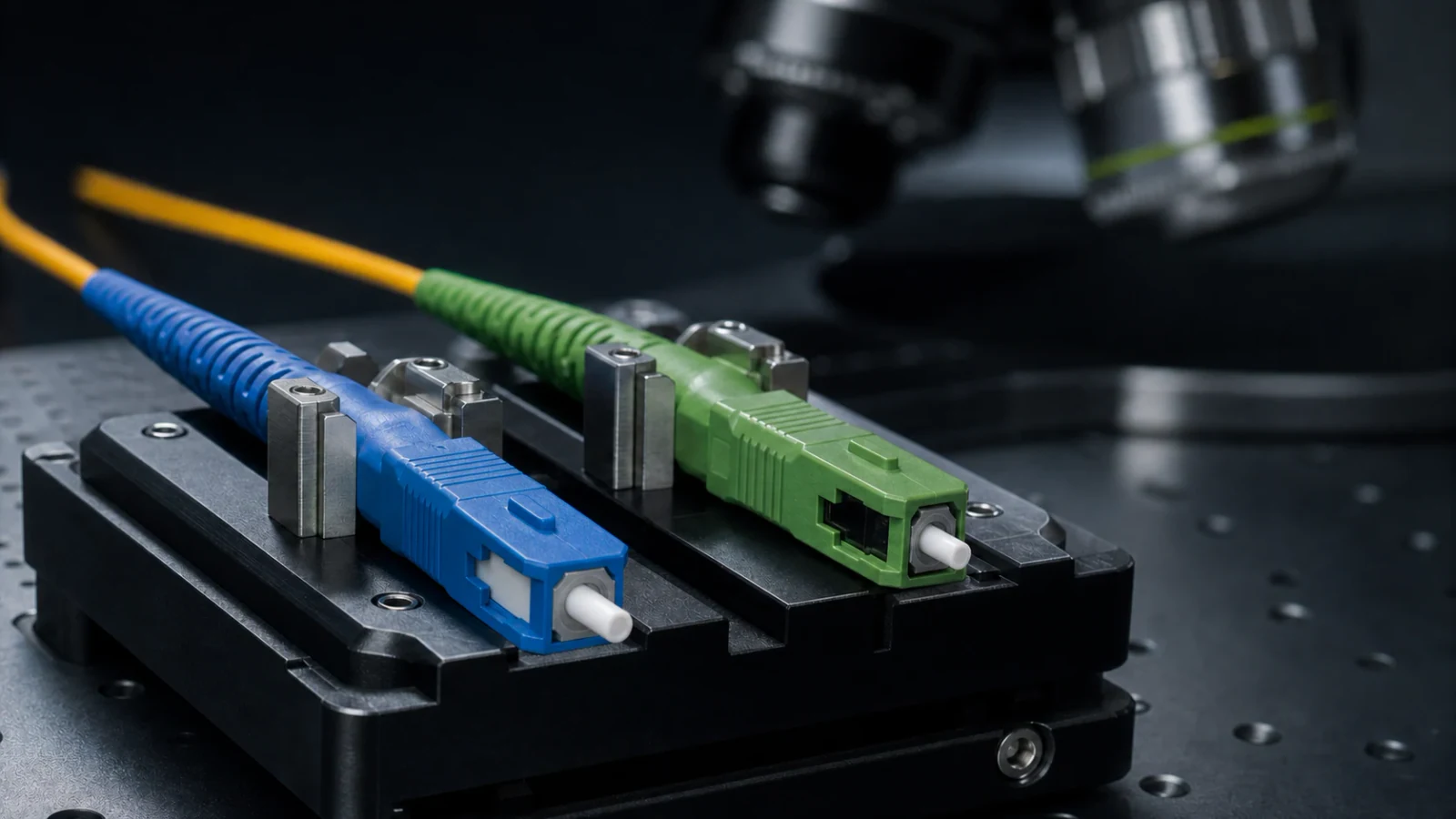
A practical engineering guide to UPC and APC fiber connector interfaces, explaining return loss, insertion loss, 8-degree angled polish, mating compatibility, applications, inspection, and test requirements.
1. UPC and APC describe the optical contact geometry
UPC means ultra physical contact and is a refined form of non-angled physical-contact polishing. The ferrule end face is polished into a controlled convex geometry so the fibre cores make physical contact when two compliant connectors are mated. APC means angled physical contact; for common 2.5 mm and 1.25 mm cylindrical zirconia ferrules, IEC 61755-3-2 defines an angled interface polished at 8 degrees.
SC, LC, FC, and other names describe connector families and mechanical interfaces. UPC or APC describes the optical polish. A complete part description therefore needs both pieces of information, such as SC/UPC or LC/APC, plus the fiber type and any required performance grade.
- Do not infer polish from connector family alone.
- Treat “PC,” “UPC,” and “APC” as distinct controlled designations.
- Check equipment-port labels and drawings before ordering patch cords.
- Use connector and adapter components designed for the same interface.
2. The main optical difference is reflected power
At any discontinuity in refractive index or physical contact, some optical power can be reflected toward the source. A well-made physical-contact interface reduces the air gap and reflection. The angled APC geometry directs much of the reflected energy away from the fiber core, which is why APC is commonly chosen for reflectance-sensitive systems.
Return loss and reflectance describe the same underlying reflected-power behaviour using different sign conventions. Return loss is normally reported as a positive decibel value, where a higher number means less reflection. Reflectance is normally negative, where a more-negative value means less reflection. Mixing these conventions can reverse a pass/fail decision.
Engineering note: Use the exact acceptance value in the governing equipment, customer, or component specification. Marketing labels such as “high return loss” are not a substitute for a measured result and defined test method.
3. APC does not automatically mean lower insertion loss
Insertion loss is the reduction in transmitted power through a connection. It is affected by core alignment, mode-field mismatch, ferrule and fiber eccentricity, end-face geometry, cleanliness, adapter alignment, wavelength, and the quality of the mating reference. Both UPC and APC connections can be designed for low attenuation when their interfaces are compliant and clean.
APC’s principal advantage is reflection control, not a universal insertion-loss advantage. Compare candidate connectors using the required performance grade, random-mate or reference-mate method, and test wavelength rather than polish name alone.
- Measure attenuation and return loss as separate characteristics.
- Inspect and clean both sides before judging optical performance.
- Use an APC reference for APC devices and a UPC reference for UPC devices.
- Record the adapter, reference cord, wavelength, and test method with the result.
4. UPC and APC must not be cross-mated
A UPC ferrule face and an APC ferrule face have incompatible contact geometries. If they are forced together in a mechanically compatible adapter, the fibre cores do not make the intended physical contact. The result can be high attenuation, high reflection, unstable readings, and damage to one or both polished surfaces.
Green is widely used to identify APC connectors and adapters, while blue is widely used for UPC single-mode interfaces. Colour is a useful operational aid but not a complete technical verification: products can be mislabelled, legacy colour practices vary, and some equipment ports are not obvious. Confirm markings, keying, documentation, and end-face geometry where necessary.
- Segregate UPC and APC components in stores, assembly, test, and field kits.
- Label both ends of patch cords and all patch-panel or equipment ports.
- Do not use a hybrid UPC-to-APC patch cord unless the system design explicitly calls for different polish at its two ends.
- Quarantine any connector that has been cross-mated until both interfaces are inspected.
5. UPC and APC comparison table
The examples in the final row are not universal mandates. Equipment vendors and network owners may specify one polish for operational consistency even when either could meet the optical budget.
| Characteristic | UPC | APC |
|---|---|---|
| End-face orientation | Non-angled physical-contact interface | Angled physical-contact interface; common cylindrical ferrules use 8° |
| Primary optical objective | Low-loss physical contact for general connections | Reduced reflected power for reflection-sensitive links |
| Insertion loss | Depends on grade, alignment, geometry, cleanliness, and test method | Depends on the same factors; not inherently lower because it is angled |
| Typical identification | Often blue for single-mode UPC | Often green |
| Mating rule | Mate only to the matching non-angled interface | Mate only to the matching angled interface |
| Common selection context | General digital transmission, data links, and test interconnects where the reflection budget permits | PON, analog/RF optical systems, sensitive sources, monitoring, or other designs with tighter reflection control |
| Inspection and cleaning | Inspect-clean-inspect before mating | Same requirement; use APC-compatible fixtures and references |
6. Choose polish from the system reflection budget
Reflections can disturb some lasers, create interference effects, add multipath noise in analog links, and reduce measurement stability. APC is therefore common in passive optical networks, analog video or RF-over-fiber systems, and other paths where back reflection is tightly controlled. It can also be selected as a network-wide standard to prevent mixed-polish field errors.
UPC remains appropriate for many digital links and equipment interfaces when it matches the transceiver or instrument port and satisfies the specified loss and reflection budget. The correct choice is the one supported end to end. Adding an APC connector to one segment does not improve a path if it creates a mismatched interface elsewhere.
- List every transmitter, receiver, splitter, filter, patch panel, test port, and demarcation in the path.
- Confirm the connector family and polish required at each interface.
- Calculate the link attenuation and reflection requirements using equipment specifications.
- Standardise adapters, reference cords, attenuators, and inspection accessories for the selected polish.
7. Inspect and test the finished connection
Polish selection cannot compensate for contamination or poor geometry. Inspect both interfaces according to the applicable criteria, clean when needed, and reinspect before mating. APC inspection fixtures and polishing holders must preserve the intended key orientation and angle; uncontrolled rotation can compromise the optical interface.
For acceptance, measure attenuation with the defined method and measure return loss or reflectance when required. Reference cords should have known quality and the same connector polish as the device under test. If a result is unstable, inspect the reference interface, adapter, and device before repeatedly reconnecting or repolishing the product.
8. Procurement checklist
A precise line item such as “LC/APC single-mode assembly, tested at the specified wavelengths to the named performance requirements” is far safer than ordering “green low-loss patch cords.” The former can be verified; the latter leaves critical interface and test details open to interpretation.
- Connector family and form factor: for example, SC, LC, FC, or another defined interface.
- Polish: UPC/non-angled or APC/angled, including any required key orientation.
- Fiber category, cable construction, jacket, length, polarity, and boot style.
- Required attenuation and return-loss or reflectance grade, including test wavelengths and method.
- Inspection criteria, geometry requirements, and any random-mate qualification.
- Colour, labels, packaging, and dust-cap controls that prevent mixed-polish installation.
Related Fibtele product categories
Final specifications, standards, compatibility, MOQ and lead time must be confirmed for the selected model before ordering.
Primary references
- IEC 61755-3-1:2024 — Non-angled single-mode connector optical-interface parameters — International Electrotechnical Commission
- IEC 61755-3-2:2024 — Angled single-mode connector optical-interface parameters — International Electrotechnical Commission
- IEC 61300-3-6:2008 — Return-loss measurement procedures — International Electrotechnical Commission
- ITU-T G.671 — Transmission characteristics of optical components and subsystems — International Telecommunication Union
Standards are revised over time. Check the current edition and the project specification before approving a design or purchase.