
MPO/MTP Cabling Design for 400G & 800G Links
Design multi-fiber trunks and breakouts from the endpoint MDI, lane map, polarity, keying, gender and channel-loss budget.
Technical page updated 2026-09-30
Quick answer
MPO/MTP cabling must be designed from the endpoint MDI and lane map. Confirm fiber count, polarity, key orientation, gender, APC/UPC, trunk or breakout construction and complete channel-loss budget before ordering.
Suitable project types
- 400G and 800G Ethernet data centers
- InfiniBand and GPU cluster fabrics
- High-density cross-connects
- Pre-terminated modular structured cabling
Inputs required before selection
- 1Endpoint transceiver or switch MDI and lane map
- 2MPO-12, MPO-16 or duplex LC interface
- 3Fiber type, reach and connector polish
- 4Polarity, keying, gender and breakout ratio
- 5Channel loss, cassette, panel and cleaning strategy
Planning workflow
- 1
Read the endpoint MDI
Start with optic or switch documentation; record lane assignment, transmit/receive direction and connector interface.
- 2
Draw the polarity
Publish a controlled A/B/C polarity drawing including key orientation, gender, cassette mapping and breakout order.
- 3
Build the channel budget
Count mating pairs, splices, cassettes, trunks and patch cords; compare maximum loss with the link requirement.
- 4
Inspect and certify
Clean and inspect each MPO end face, verify polarity and perform channel IL/RL testing with traceable records.
Selection checklist
- MPO-12, MPO-16, MTP or duplex LC
- OS2, OM4 or OM5 fiber and reach
- APC/UPC, male/female and key orientation
- Type A, Type B, Type C or custom polarity
- Trunk, breakout, cassette and patch-panel mapping
Important limits
- A cable labeled 400G or 800G is incomplete without an endpoint and lane-map definition.
- MTP is a connector brand and MPO is an interface family; verify exact performance and compatibility.
- Polarity errors can pass continuity checks while breaking lanes; use a controlled drawing and test.
Products mapped to this workflow
These products are relevant to specific stages of the workflow. Final suitability depends on the configuration and acceptance criteria above.
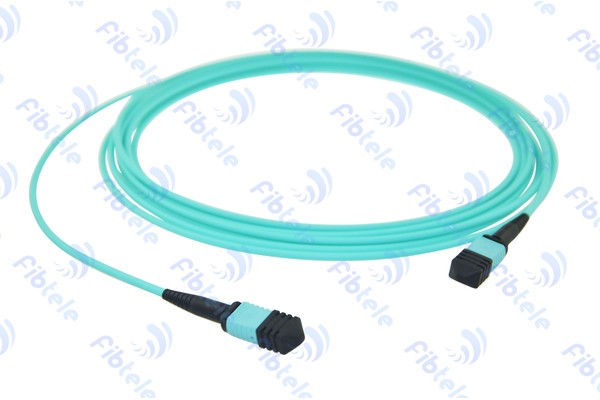
MPO Fiber Optic Patch Cord A/B/C Type
MPO/MTP trunk multi-core cable assemblies for rapid deployment of high density backbone cabling in data centers.
View Details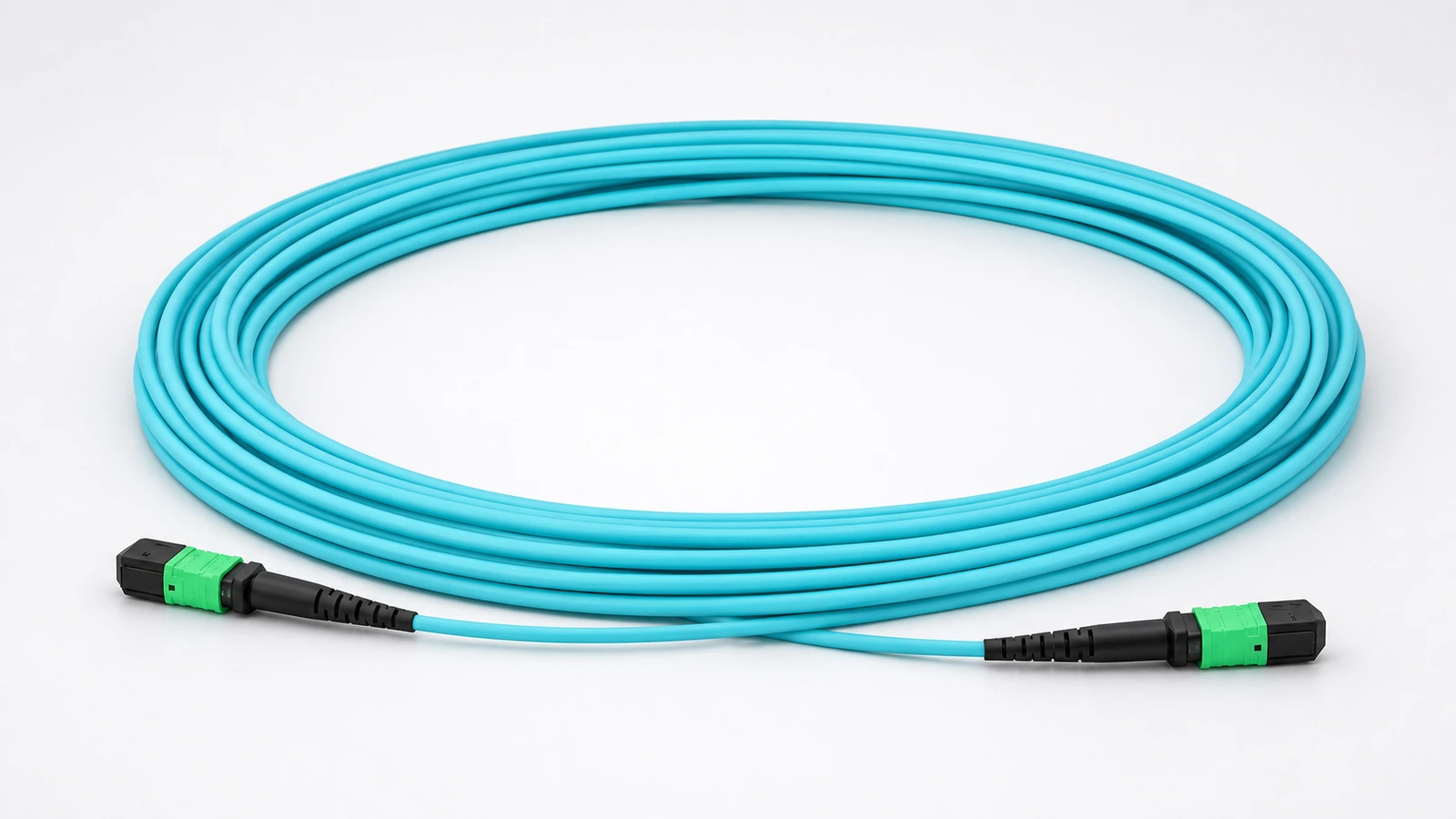
8-Fiber OM4 MPO-12/APC Type-B Cable for AI Clusters
Low-loss 8-fiber OM4 cable with MPO-12/APC female connectors and Type-B polarity for short-reach GPU, DPU, switch, and storage parallel-optics links.
View Details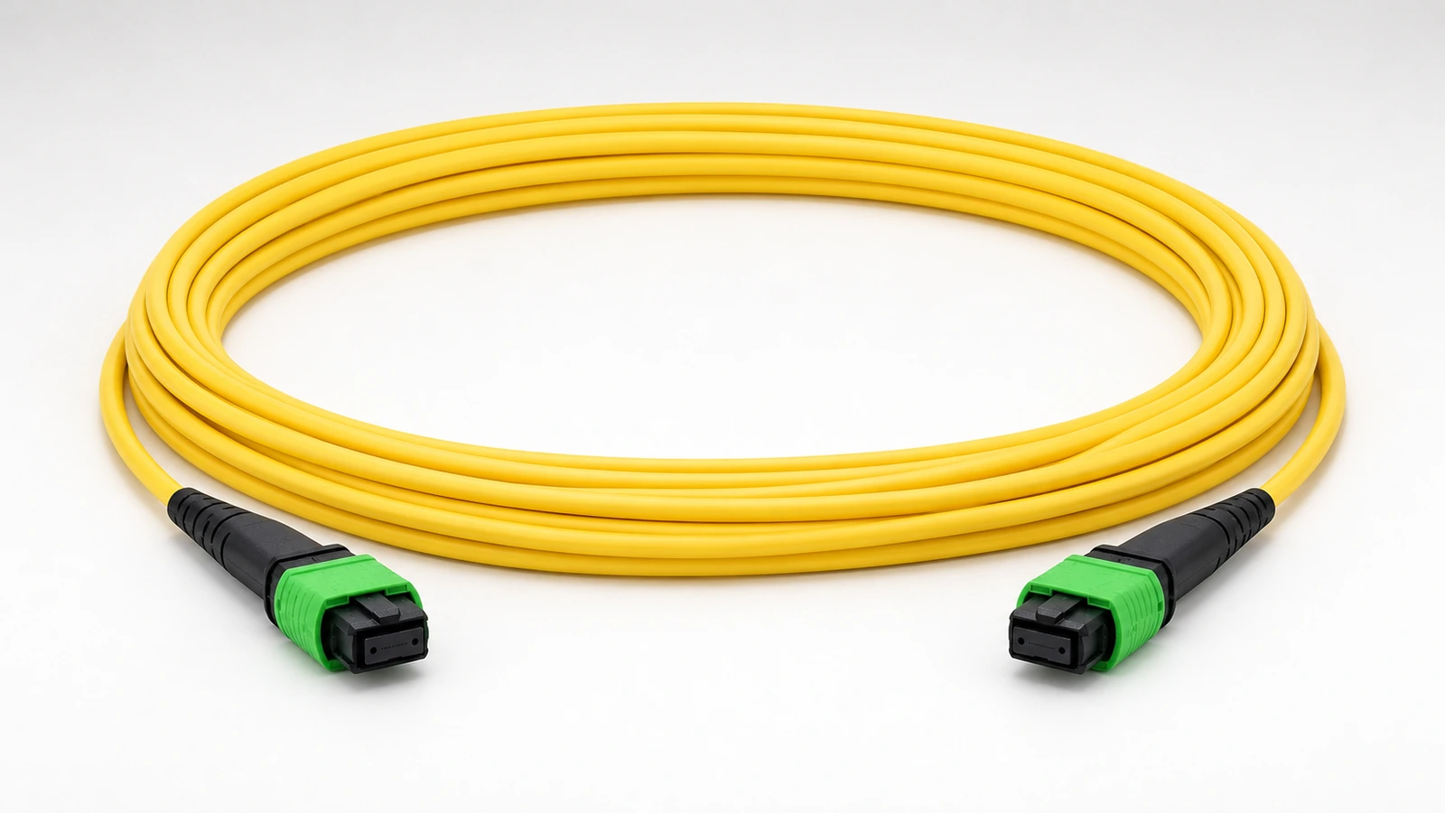
8-Fiber OS2 MPO-12/APC Type-B Cable for 400G/800G DR Optics
8-fiber OS2 single-mode MPO-12/APC Type-B assembly for inter-rack and leaf-spine parallel-optics links using DR-class transceivers.
View Details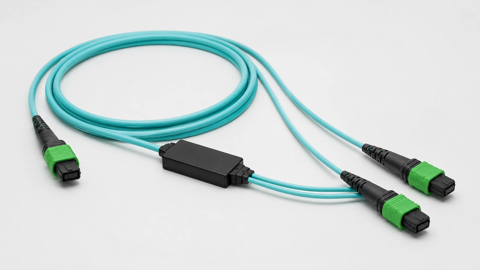
OM4 MPO-12/APC 1-to-2 Breakout Cable
OM4 multimode 1-to-2 MPO-12/APC breakout assembly for converting a four-channel parallel-optics path into two two-channel branches in supported OSFP and QSFP112 architectures.
View Details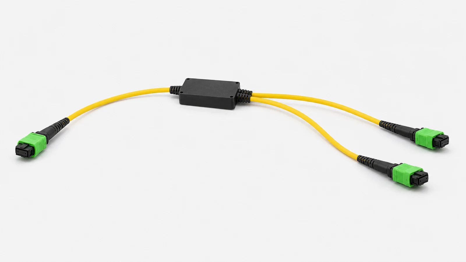
OS2 MPO-12/APC 1-to-2 Breakout Cable
OS2 single-mode 1-to-2 MPO-12/APC breakout assembly for supported DR parallel-optics designs that split one four-channel path into two two-channel branches.
View Details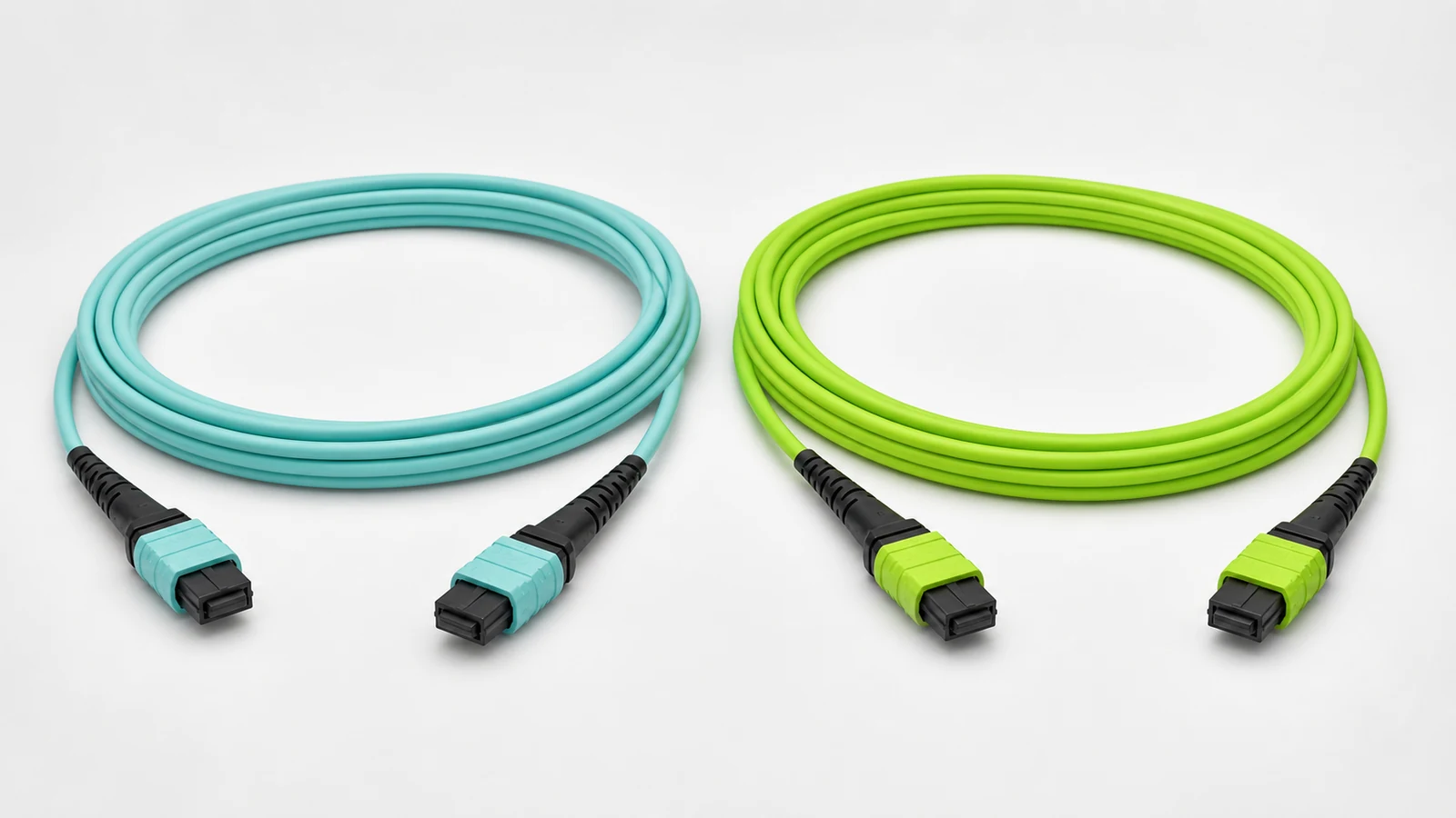
16-Fiber OM4/OM5 MPO-16 Cable for Native 800G Parallel Optics
16-fiber OM4 or OM5 MPO-16 cable assembly for native eight-lane multimode parallel-optics interfaces such as 800GBASE-VR8 and 800GBASE-SR8.
View Details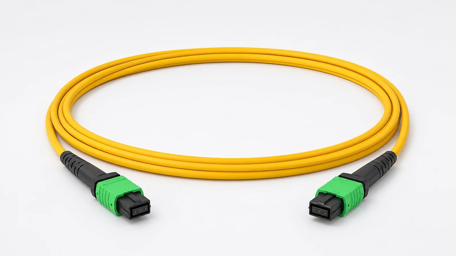
16-Fiber OS2 MPO-16 Cable for 800G DR8 and Emerging 1.6T
16-fiber OS2 MPO-16 parallel-optics assembly for 800G DR8-class links and infrastructure planning for emerging 1.6T optical interfaces.
View DetailsRelated technical guides
Primary references
- IEC 61754-7 — MPO connector interfaces
International Electrotechnical Commission
- TIA-568.3 — Optical fiber cabling and components
Telecommunications Industry Association
Frequently asked questions
Use the exact transceiver MDI, lane count, breakout requirement, panel system and channel design. Connector fiber count follows the endpoint, not a generic speed label.
Type B reverses fiber positions across the mating interfaces. The correct polarity depends on the complete channel and endpoint lane map.
A contaminated multi-fiber end face can affect several lanes and damage the mating interface. Inspect and clean before every connection and test.
Send the project inputs for configuration review
Include endpoint models, interfaces, quantities, route or process constraints, required test documents and acceptance criteria.