

AI Data Center Fiber Cabling
Engineer GPU-cluster cabling from endpoint optics, MPO interface, lane mapping, topology, pathway density and the complete channel-loss budget.
Technical page updated 2026-07-23
Quick answer
AI clusters do not use one universal fibre cable. The correct assembly is derived from the switch and accelerator optics, protocol, lane rate, MDI, topology, reach and channel-loss budget. MPO-12, MPO-16 and duplex LC can all be valid in different designs.
Suitable project types
- GPU and accelerator cluster front-end or back-end network cabling
- 400G and 800G Ethernet or InfiniBand structured-cabling studies
- MPO trunk and breakout designs for leaf, spine and rail-optimised fabrics
- Migration planning toward new 800G and 1.6T platforms
Inputs required before selection
- 1Approved network architecture and endpoint bill of materials
- 2Exact switch, adapter, DPU and transceiver part numbers
- 3Protocol, lane rate, straight or breakout mode and oversubscription plan
- 4Fibre type, MDI, connector polish, gender, polarity and maximum reach
- 5Patch-panel, pathway, airflow, service-loop and cleaning constraints
Planning workflow
- 1
Start from the network BOM
Freeze ports and transceivers before choosing the passive cable. Nominal speed alone is not enough to determine an interface.
- 2
Create a lane-level connectivity matrix
Document every transmit and receive lane, connector position, polish, gender, key orientation and breakout endpoint.
- 3
Engineer the physical path
Model patch panels, trunks, mating points, pathway fill, bend control, service access and the full channel-loss budget.
- 4
Pilot and validate
Approve samples against the equipment vendor guide, inspect and test the channel, verify labelling, then release the production BOM.
Selection checklist
- Endpoint MDI and populated fibre positions
- MPO-12 versus MPO-16 or duplex LC
- APC versus UPC, male versus female and key orientation
- Type-A, Type-B or application-specific lane mapping
- Straight, 1-to-2 or other breakout arrangement
- Channel loss, reach, patch-panel count and cleaning strategy
Important limits
- Do not describe a cable as 400G, 800G or 1.6T compatible without the endpoint and lane-map context.
- Platform generations may use different optics at the same nominal port speed.
- All final assemblies require vendor-document review and a controlled polarity drawing.
Products mapped to this workflow
These products are relevant to specific stages of the workflow. Final suitability depends on the configuration and acceptance criteria above.
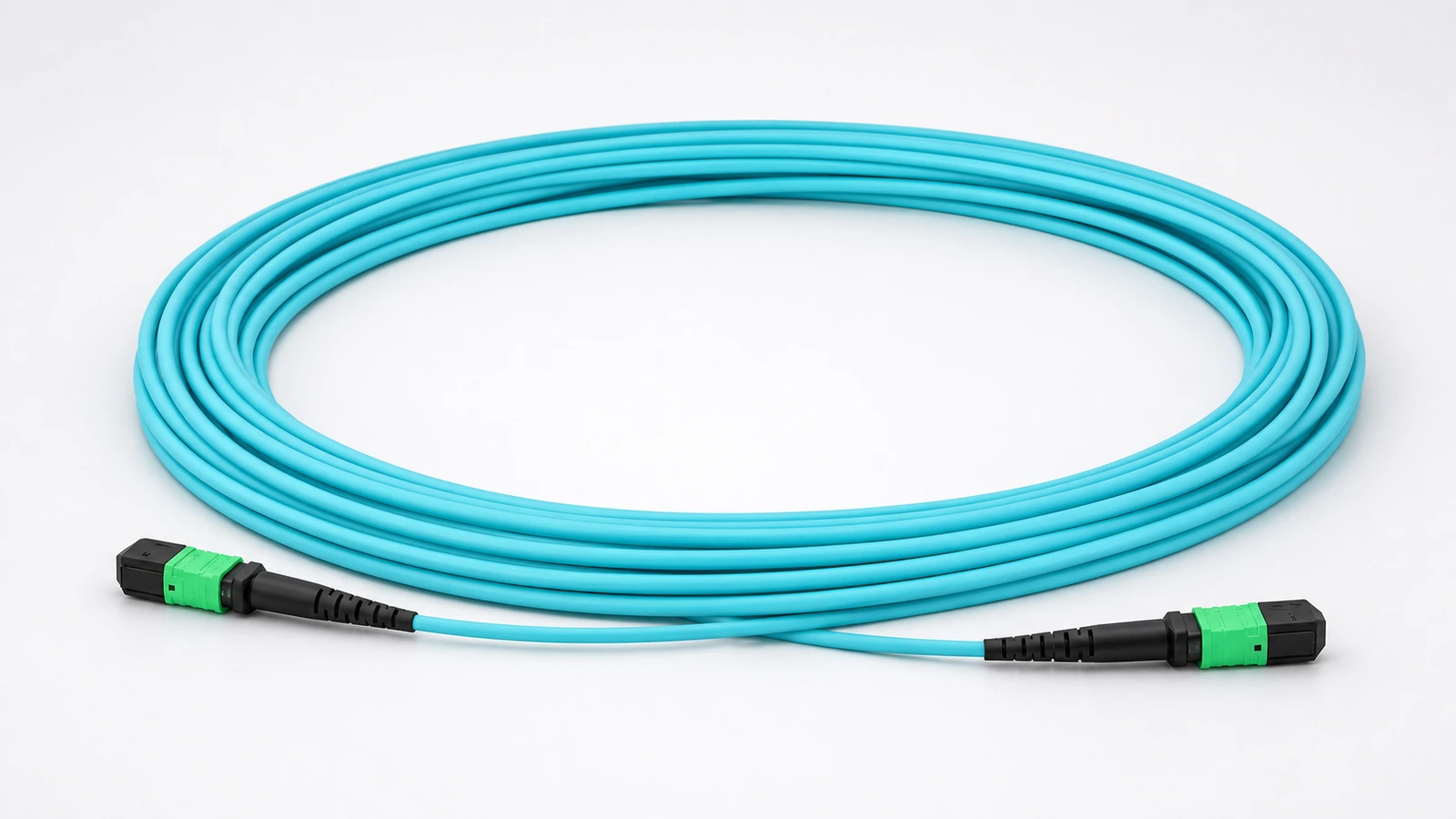
8-Fiber OM4 MPO-12/APC Type-B Cable for AI Clusters
Low-loss 8-fiber OM4 cable with MPO-12/APC female connectors and Type-B polarity for short-reach GPU, DPU, switch, and storage parallel-optics links.
View Details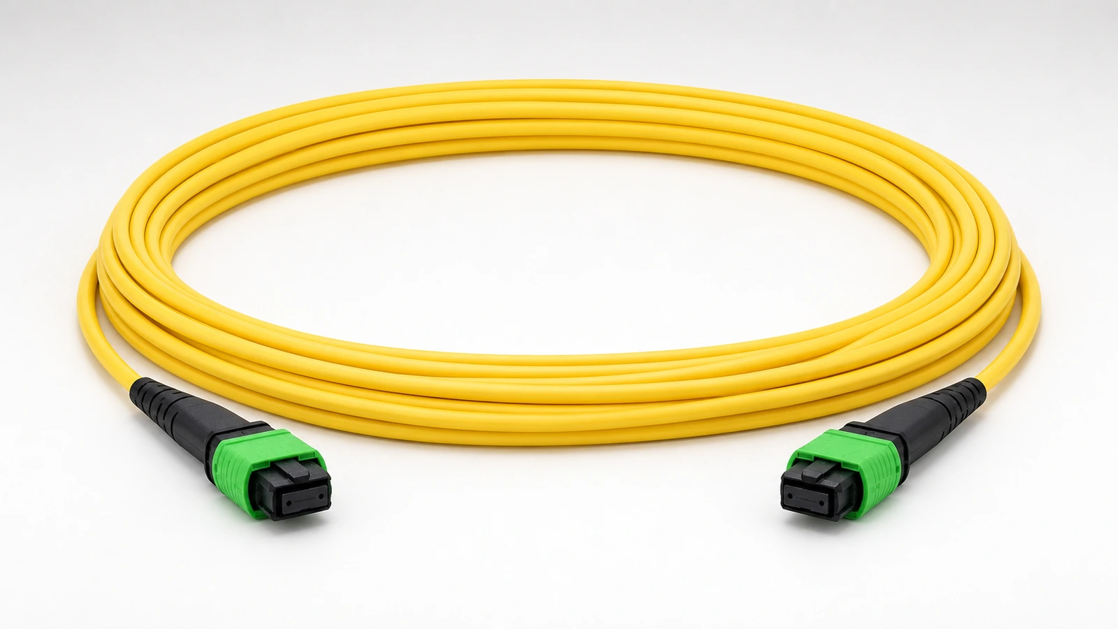
8-Fiber OS2 MPO-12/APC Type-B Cable for 400G/800G DR Optics
8-fiber OS2 single-mode MPO-12/APC Type-B assembly for inter-rack and leaf-spine parallel-optics links using DR-class transceivers.
View Details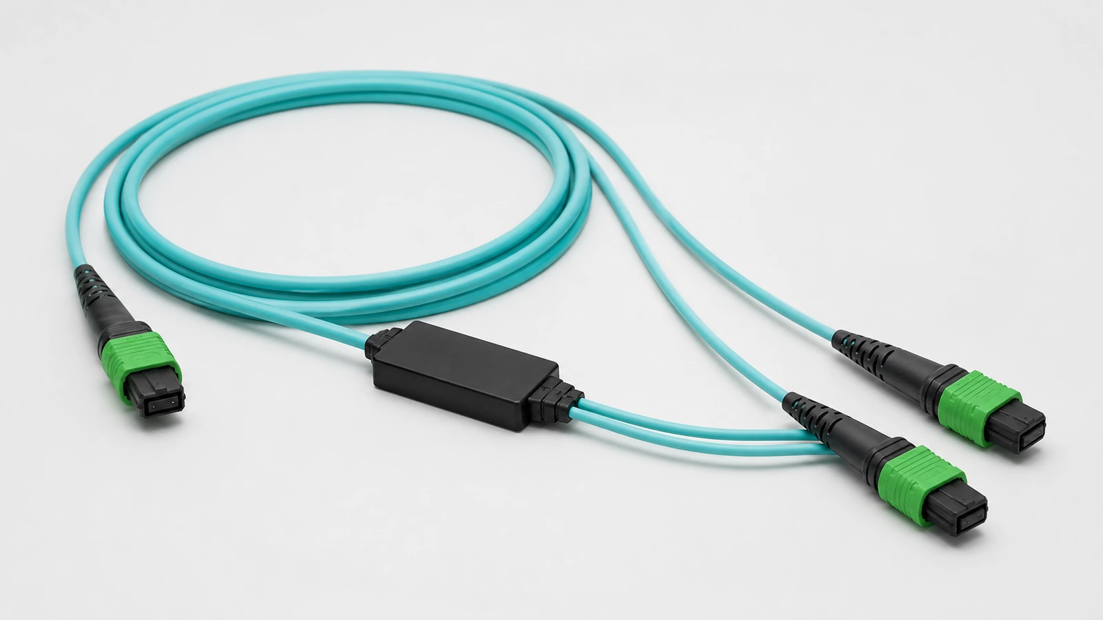
OM4 MPO-12/APC 1-to-2 Breakout Cable
OM4 multimode 1-to-2 MPO-12/APC breakout assembly for converting a four-channel parallel-optics path into two two-channel branches in supported OSFP and QSFP112 architectures.
View Details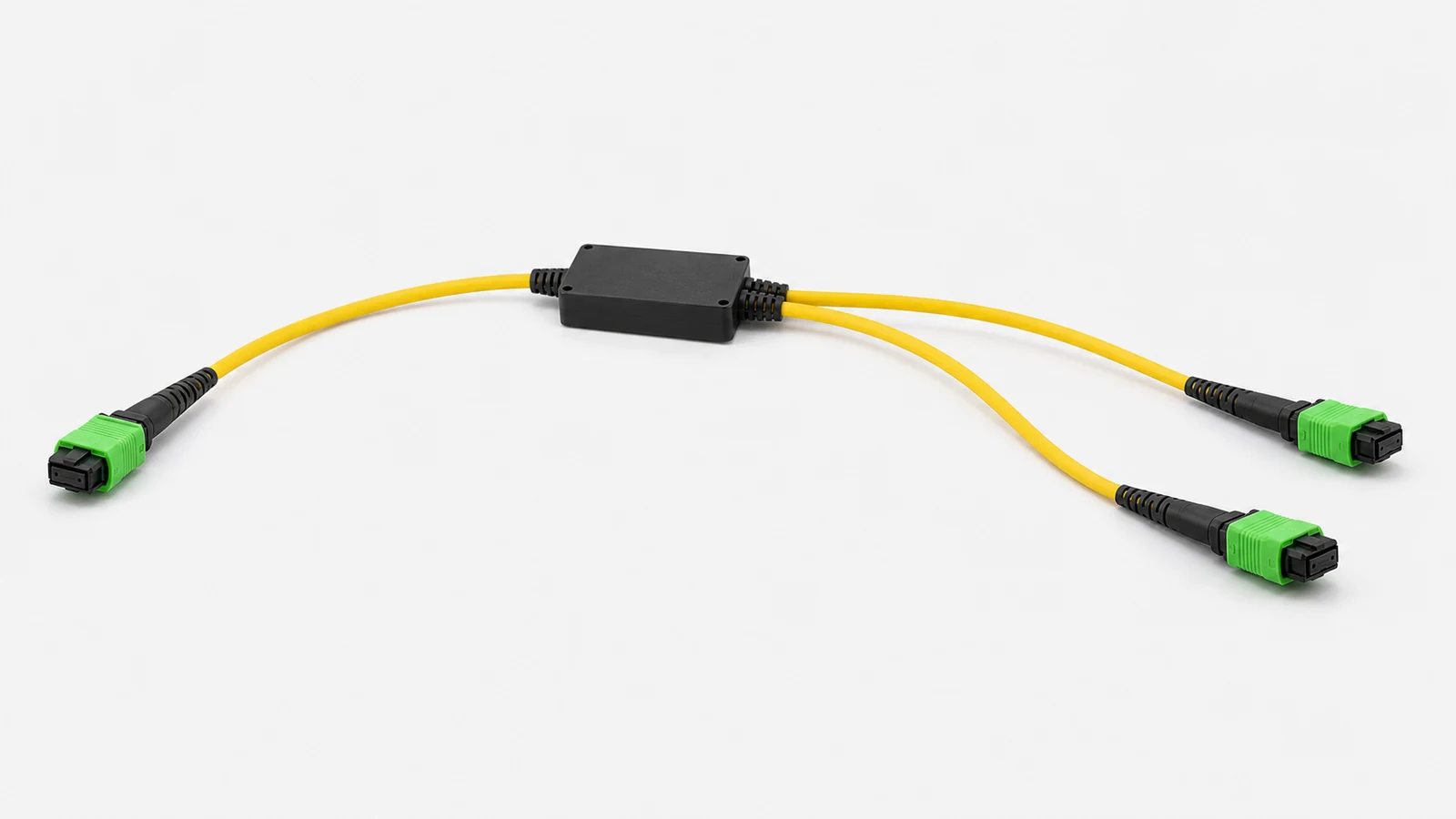
OS2 MPO-12/APC 1-to-2 Breakout Cable
OS2 single-mode 1-to-2 MPO-12/APC breakout assembly for supported DR parallel-optics designs that split one four-channel path into two two-channel branches.
View Details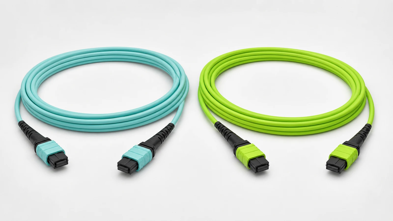
16-Fiber OM4/OM5 MPO-16 Cable for Native 800G Parallel Optics
16-fiber OM4 or OM5 MPO-16 cable assembly for native eight-lane multimode parallel-optics interfaces such as 800GBASE-VR8 and 800GBASE-SR8.
View Details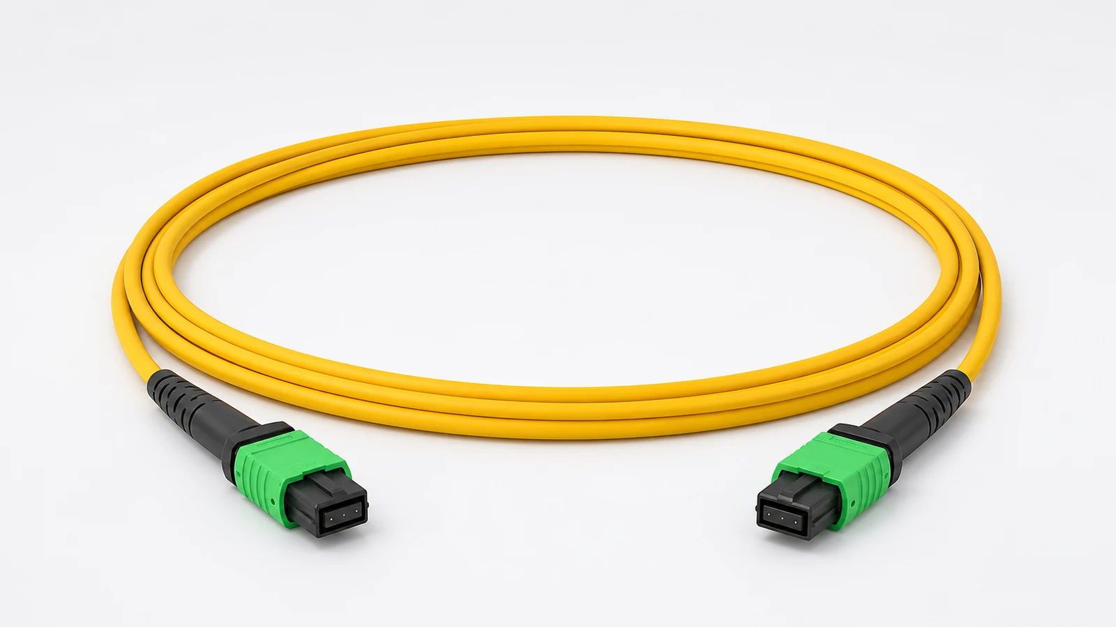
16-Fiber OS2 MPO-16 Cable for 800G DR8 and Emerging 1.6T
16-fiber OS2 MPO-16 parallel-optics assembly for 800G DR8-class links and infrastructure planning for emerging 1.6T optical interfaces.
View Details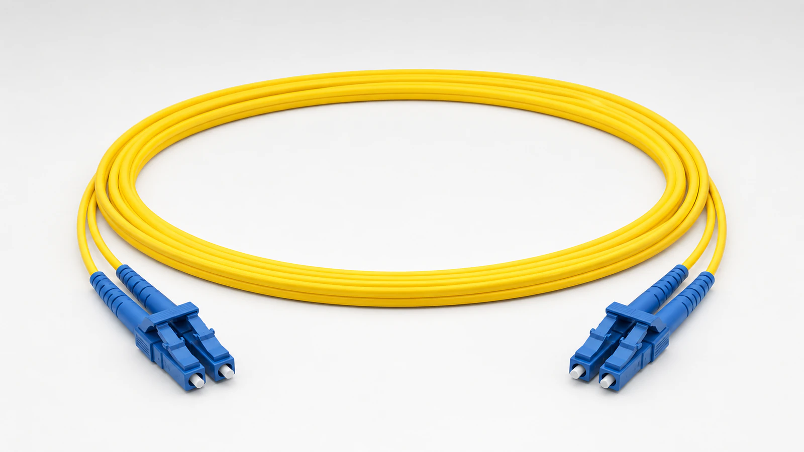
OS2 Duplex LC Fiber Patch Cord for FR4/LR4 and DCI
Duplex OS2 LC/UPC patch cord for wavelength-multiplexed FR4, LR4, and data center interconnect links where the selected optical modules use duplex LC interfaces.
View DetailsRelated technical guides
Primary references
- IEEE 802.3df-2024 — 400 Gb/s and 800 Gb/s Ethernet operation
IEEE Standards Association
- NVIDIA Networking interconnect documentation
NVIDIA Networking
- Structured cabling requirements for InfiniBand and 400/800G Ethernet
NVIDIA Networking
Frequently asked questions
Both multimode and single-mode fibre are used. The choice depends on the transceiver, reach, topology, pathway, power and migration plan—not on the AI workload label alone.
Parallel-optics interfaces and high-density trunks can use MPO connectors to carry multiple transmit and receive lanes. The fibre count, polish, keying and lane map still depend on the selected optics.
Begin with the exact platform and optical module documentation. Confirm lane rate, MDI, port mode, fibre type, reach and breakout behaviour before defining any passive cable assembly.
Send the project inputs for configuration review
Include endpoint models, interfaces, quantities, route or process constraints, required test documents and acceptance criteria.