
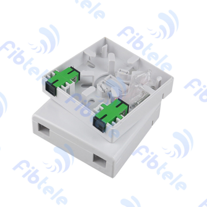
PLC Fiber Splitter Selection by Ratio & Loss Budget
Match PLC split ratio, wavelength, package, connector and maximum loss to a documented GPON or XGS-PON ODN budget.
Technical page updated 2026-09-30
Quick answer
Choose a PLC splitter after fixing PON wavelengths, split ratio, topology, package, connector policy and loss budget. Validate maximum insertion loss, uniformity, return loss, directivity and environmental rating for the exact part.
Suitable project types
- Centralized and distributed FTTH splitting
- GPON, XGS-PON and coexistence ODNs
- Rack, cassette, ABS, mini-tube and bare-fiber assemblies
- New builds and ODN expansion
Inputs required before selection
- 1PON technology, wavelength range and optical class
- 2Split ratio, stage count and port reserve
- 3Package, connector and splice method
- 4Maximum loss, uniformity, return loss and PDL
- 5Temperature, humidity and installation environment
Planning workflow
- 1
Define the topology
Set centralized, distributed or cascaded splitter locations and subscriber and reserve ports.
- 2
Calculate loss
Include splitter maximum loss, connectors, splices, fiber attenuation, coexistence elements and engineering margin.
- 3
Select package
Match mini-tube, ABS, cassette, rack or bare-fiber package to the enclosure, tray and service workflow.
- 4
Verify the lot
Check wavelength, ratio, loss, uniformity, PDL, connector workmanship and batch test records before release.
Selection checklist
- 1x2 to 1x64 or project-specific ratio
- Operating wavelengths and PON class
- Maximum insertion loss and uniformity
- Package, pigtail, connector and fiber length
- Environmental and test-report requirements
Important limits
- Typical loss values are not a substitute for the exact maximum loss of the ordered ratio.
- A splitter cannot be approved without the complete ODN loss budget.
- Confirm connector polish, pigtail length and enclosure compatibility on the controlled drawing.
Products mapped to this workflow
These products are relevant to specific stages of the workflow. Final suitability depends on the configuration and acceptance criteria above.
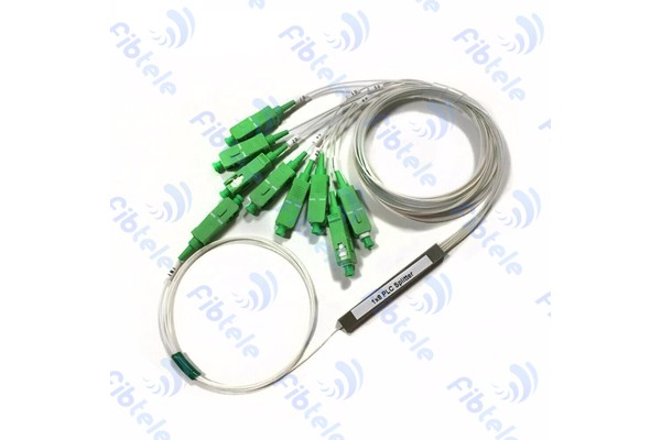
Mini Tube PLC Splitter
PLC splitter based on silicon dioxide waveguides for EPON, BPON and GPON network terminal equipment connections.
View Details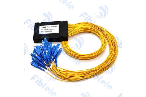
ABS Splitter
Planar light-wave circuit PLC splitter fabricated using silica optical waveguide technology in ABS box packaging.
View Details
Cassette Splitter
PLC splitter in cassette packaging for connecting local equipment and terminal equipment in EPON, BPON and GPON networks.
View Details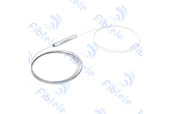
Bare Fiber Splitter
Bare fiber PLC splitter for installation in various pigtail boxes, test instruments and WDM systems.
View Details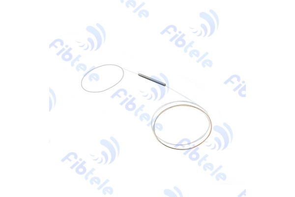
FBT Coupler
FBT coupler that bundles and melts fibers on pull-cone machine with real-time split ratio monitoring for precise splitting.
View DetailsRelated technical guides
Primary references
- ITU-T G.671 — Optical components and subsystems
International Telecommunication Union
Frequently asked questions
PLC splitters provide scalable multi-way splitting with more uniform outputs, while FBT couplers are often used for lower split counts or specific ratios. Topology and loss budget decide the fit.
Compare the required take rate, reach, optical class, port reserve and loss budget. A higher split ratio is not automatically better for coverage or cost.
State ratio, wavelengths, maximum loss, uniformity, PDL, return loss, package, pigtail, connector, operating temperature and test-document format.
Send the project inputs for configuration review
Include endpoint models, interfaces, quantities, route or process constraints, required test documents and acceptance criteria.