
Fiber Optic Patch Cord Selection & Custom Assemblies
Specify connector, fiber mode, polish, polarity, length, jacket and optical acceptance for telecom, FTTH and data center patch cords.
Technical page updated 2026-09-30
Quick answer
Select a patch cord from the endpoint interface, single-mode or multimode fiber, polish, polarity, length, environment and insertion/return-loss limits. Approve a controlled drawing and an end-face plus optical test record before release.
Suitable project types
- Telecom and carrier interconnects
- FTTH and ODN cabinets
- Data center cross-connects
- Industrial and harsh-environment links
Inputs required before selection
- 1Connector type, keying, gender and polish at both ends
- 2Fiber mode, core count, jacket and bend radius
- 3Length, fanout, polarity and labeling
- 4Insertion-loss, return-loss and end-face limits
- 5Packing and lot-traceability requirements
Planning workflow
- 1
Map the endpoints
Record the equipment, adapter or panel interface, key orientation and connector gender on each end.
- 2
Choose the cable build
Match OS2, OM3, OM4 or another specified fiber and set jacket, bend and breakout requirements.
- 3
Control polarity and length
Publish an assembly drawing showing polarity, breakout order, reference length and labels.
- 4
Inspect and test
Clean and inspect each end face, measure insertion and return loss, and retain the report.
Selection checklist
- LC, SC, FC, ST, E2000, MPO/MTP or rugged interface
- OS2, OM3/OM4 or project-specified fiber
- UPC or APC polish, key orientation and gender
- Simplex, duplex, breakout or multi-fiber trunk
- IL/RL, geometry, cleanliness and labeling acceptance
Important limits
- Nominal connector compatibility does not prove polarity, gender or key orientation.
- Insertion loss depends on the reference method, adapters and test wavelength.
- Confirm bend, jacket, flame and environmental requirements for the installed route.
Products mapped to this workflow
These products are relevant to specific stages of the workflow. Final suitability depends on the configuration and acceptance criteria above.
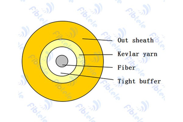
Fiber Optic Patch Cord Cable
Quality simplex and duplex fiber optic patch cord cables with tight buffer for indoor applications.
View Details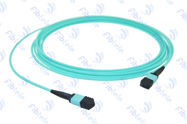
MPO Fiber Optic Patch Cord A/B/C Type
MPO/MTP trunk multi-core cable assemblies for rapid deployment of high density backbone cabling in data centers.
View Details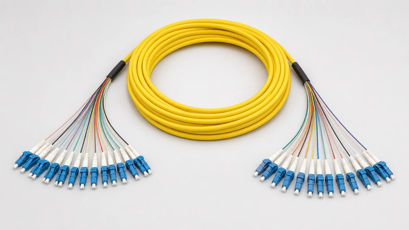
Breakout Fiber Optic Patch Cord SC/LC/FC/ST
Breakout fiber patch cord for building backbone or horizontal distribution in harsh environments.
View Details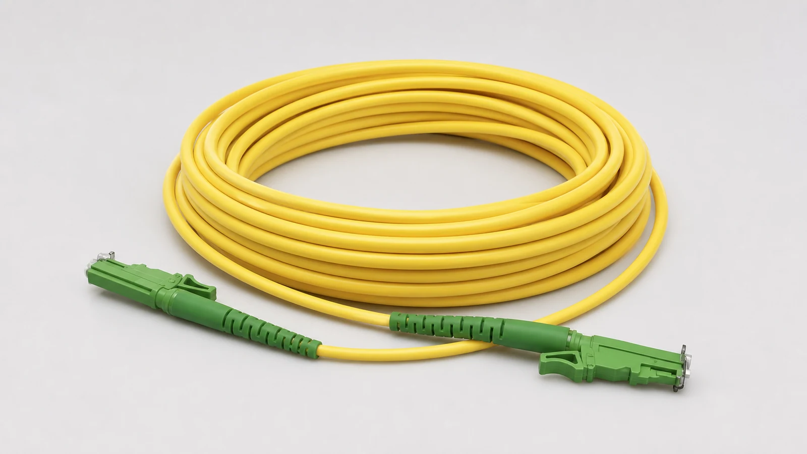
E2000 Fiber Optic Patch Cord
E2000/APC patch cord providing optical connection for fiber optic electronics with quick routing capability.
View Details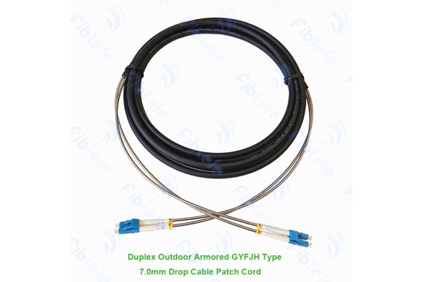
Armored Fiber Optic Patch Cord
Armored fiber optic patch cord with stainless steel armor for enhanced protection in harsh environments.
View Details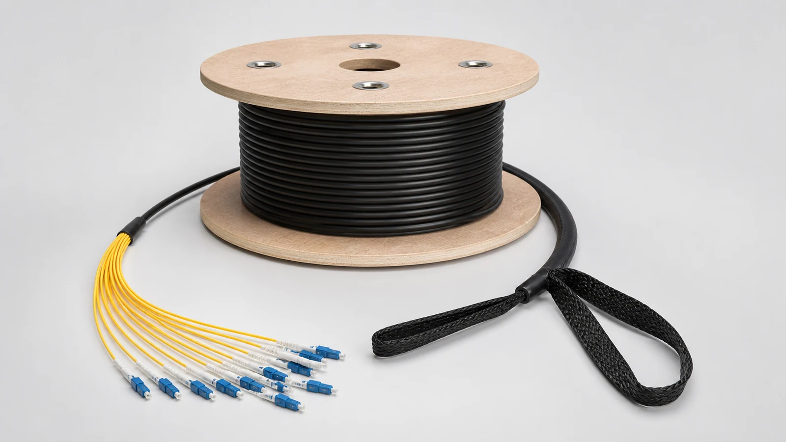
Pre-terminated Patch Cord
Factory-terminated fiber optic patch cord for quick plug-and-play installation in data centers.
View DetailsRelated technical guides
Primary references
- IEC 61754 — Fibre optic connector interfaces
International Electrotechnical Commission
- IEC 61300-3-35 — Connector end-face inspection
International Electrotechnical Commission
Frequently asked questions
Provide both interfaces, fiber mode, polish, gender, polarity, length, jacket, bend requirement and IL/RL acceptance. Include a drawing for breakout or MPO assemblies.
No. The polish angle and return-loss behavior differ. Use the polish required by the equipment and keep APC and UPC interfaces separated.
Ship the approved drawing, part numbers, inspection and optical test results, labels and a lot-level certificate or report.
Send the project inputs for configuration review
Include endpoint models, interfaces, quantities, route or process constraints, required test documents and acceptance criteria.