
Fiber Optic Adapter Selection for Panels, Boxes & ODFs
Match SC, LC, FC, ST, E2000 or bare-fiber adapters by polish, sleeve, flange, mounting and cleanliness requirements.
Technical page updated 2026-09-30
Quick answer
Match an adapter to the connector interface, polish, alignment sleeve, panel cutout and insertion-loss target. Confirm ferrule material, keying, flange, dust protection and mounting dimensions on the drawing.
Suitable project types
- ODF and rack patch panels
- FTTH boxes and termination points
- Data center high-density panels
- Test benches and production fixtures
Inputs required before selection
- 1Connector family and polish
- 2Sleeve material and alignment tolerance
- 3Simplex, duplex, quad or shuttered format
- 4Panel cutout, flange, screw or snap mounting
- 5Mating cycles, loss, return loss and environmental requirements
Planning workflow
- 1
Confirm mating interfaces
List connector families, ferrule sizes, polish type, keying and shutter requirements.
- 2
Fit the panel
Verify cutout, flange, screw pitch, latch clearance and fiber bend space against the enclosure or ODF.
- 3
Set performance
Specify alignment sleeve, insertion loss, return loss, durability and material requirements.
- 4
Control cleanliness
Inspect sleeves and caps, define cleaning and dust-control practices, and approve sample fit before volume release.
Selection checklist
- SC, LC, FC, ST, E2000 or bare-fiber interface
- PC, UPC or APC polish
- Ceramic, phosphor-bronze or specified sleeve
- Simplex, duplex, quad, shutter and flange type
- Panel dimensions, loss, durability and dust protection
Important limits
- Adapters do not correct incompatible polish, keying or connector geometry.
- Insertion loss depends on both mating connectors and cleanliness.
- Confirm the exact panel cutout and mounting method with the enclosure supplier.
Products mapped to this workflow
These products are relevant to specific stages of the workflow. Final suitability depends on the configuration and acceptance criteria above.
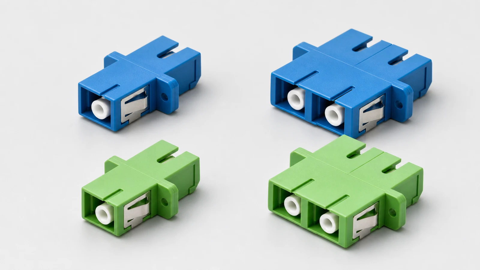
SC Fiber Adaptor
SC fiber optic adaptor providing cable-to-cable or cable-to-equipment connections with wide range of mating sleeves.
View Details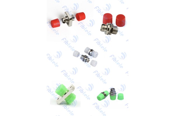
FC Adaptor
FC fiber optic adaptor with insertion loss ≤0.2dB, operating temperature -45°C to +75°C, 1000 times durability.
View Details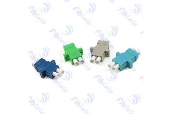
LC Adaptor
LC DX adapter with flange SC-type, insertion loss ≤0.3dB, operating temperature -40°C to 70°C.
View Details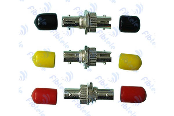
ST Adaptor
ST fiber optic adaptor for bayonet-style fiber connections in telecom and LAN applications.
View Details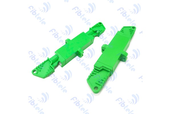
E2000 Adaptor
E2000 fiber optic adaptor with integrated dust shutter for clean and protected fiber connections.
View Details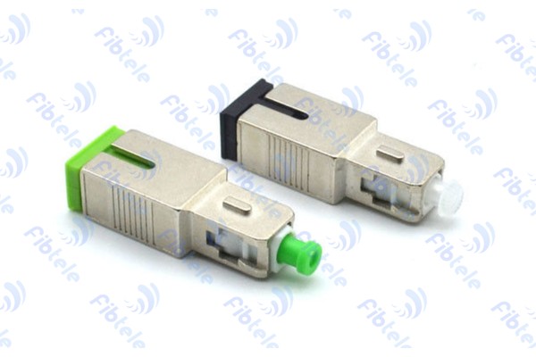
Bare Fiber Adapter
Fiber optic bare fiber adapter (bulkhead) for joining two fiber optic patch cables together, available in singlemode and multimode.
View DetailsRelated technical guides
Primary references
- IEC 61754 — Fibre optic connector interfaces
International Electrotechnical Commission
Frequently asked questions
The shell may look similar, but APC and UPC interfaces should not be mixed. Specify the correct polish and label the panel clearly.
LC duplex or another high-density interface is common, but the final choice depends on port density, polarity, bend space, transceiver and panel system.
Use protective caps, clean packaging, lot identification and a defined cleanliness inspection so sleeves are not contaminated before installation.
Send the project inputs for configuration review
Include endpoint models, interfaces, quantities, route or process constraints, required test documents and acceptance criteria.