
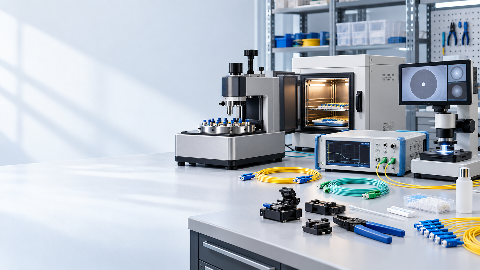
Fiber Optic Polishing Machine Selection & Process Control
Choose polishing machines by connector fixture, ferrule count, polish recipe, throughput, inspection and optical acceptance.
Technical page updated 2026-09-30
Quick answer
A polishing machine is selected from connector geometry, ferrule count, polish type, batch size and end-face or optical acceptance. Sustainable output depends on fixtures, film, pressure, cleaning, inspection and rework control as much as motor speed.
Suitable project types
- LC, SC, FC, ST and E2000 patch cord lines
- MPO/MTP multi-fiber production cells
- Pilot lines and contract manufacturing
- Capacity expansion and process automation
Inputs required before selection
- 1Connector families, ferrule geometry and polish
- 2Single-fiber or multi-fiber fixture count
- 3Target daily volume, takt time and changeovers
- 4End-face, geometry, IL/RL and cleanliness limits
- 5Power, air, consumables, operator and traceability requirements
Planning workflow
- 1
Define the work cell
List connector mix, ferrule geometry, batch size, operator flow and required fixture inventory.
- 2
Set the recipe
Control film sequence, pressure, speed, dwell, cleaning method and changeover rules for each connector.
- 3
Inspect the result
Use end-face inspection and geometry measurement where required; visual appearance alone is not optical acceptance.
- 4
Qualify and release
Run repeatability, yield and rework trials, then tie recipe, consumable lot, operator and test results to production.
Selection checklist
- Connector and ferrule fixture compatibility
- PC, UPC, APC or MPO polish process
- Capacity, batch size and changeover time
- Recipe, pressure and consumable control
- Inspection, geometry, IL/RL and data traceability
Important limits
- Machine nameplate throughput is not line throughput; yield, changeover and inspection are part of capacity.
- MPO/MTP polishing needs dedicated fixtures and geometry or end-face controls.
- Qualify the exact connector, film and process recipe before quoting output.
Products mapped to this workflow
These products are relevant to specific stages of the workflow. Final suitability depends on the configuration and acceptance criteria above.
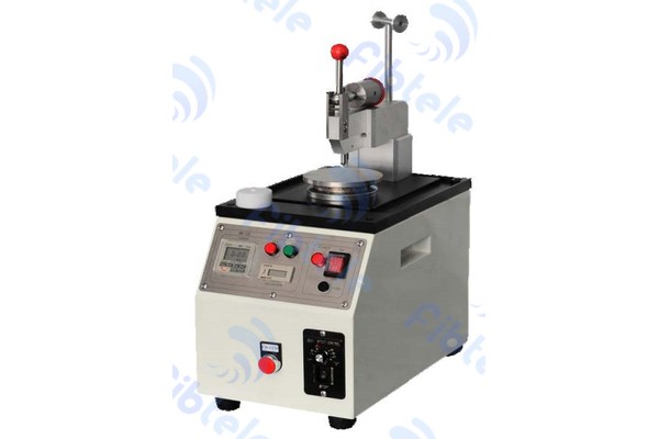
Round Type Polishing Machine
High-precision automatic round type fiber optic connector polishing machine with programmable polishing parameters for mass production.
View Details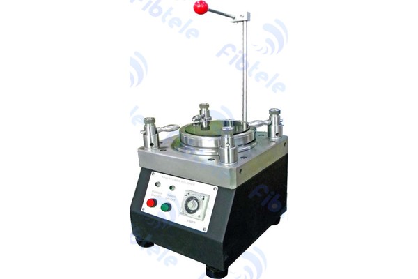
Square Type Polishing Machine
Square type fiber optic polishing machine for batch processing of fiber optic connectors with stable and reliable performance.
View Details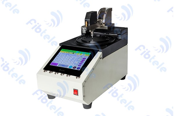
MPO/MTP Polishing Machine
Specialized polishing machine designed for MPO/MTP multi-fiber connectors with high precision alignment.
View Details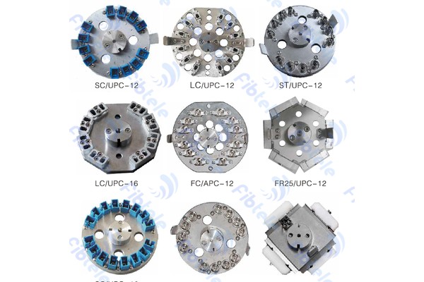
Round Type Fiber Optic Polishing Jig
Round type polishing jig for securing fiber optic connectors during the polishing process.
View Details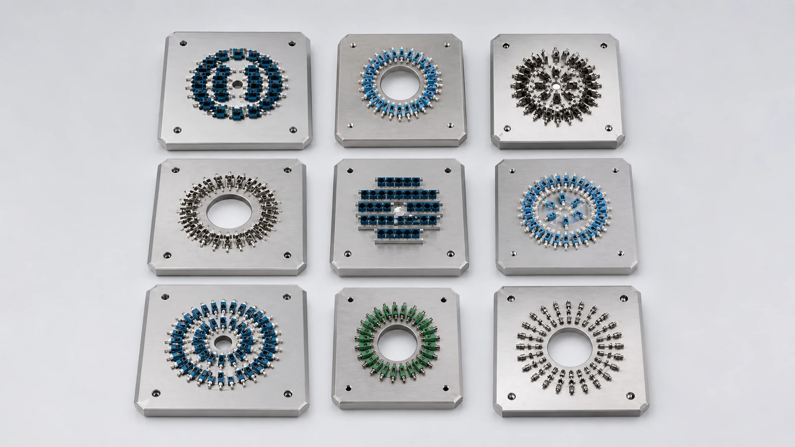
Square Fiber Optic Polishing Jig
Square fiber optic polishing jig for securely holding connector fixtures during precision batch polishing.
View Details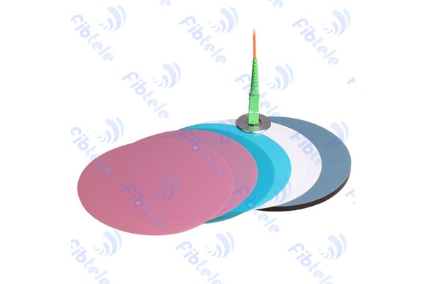
Polishing Film
Multi-grade fiber optic polishing films for achieving optical-grade end face finish on fiber connectors.
View Details
Final Type Polishing Film ADS
ADS final type polishing film for the last polishing step to achieve ultra-smooth connector end face.
View Details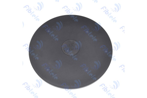
Polishing Rubber Pad
Elastomeric polishing rubber pad providing uniform pressure distribution during connector polishing.
View Details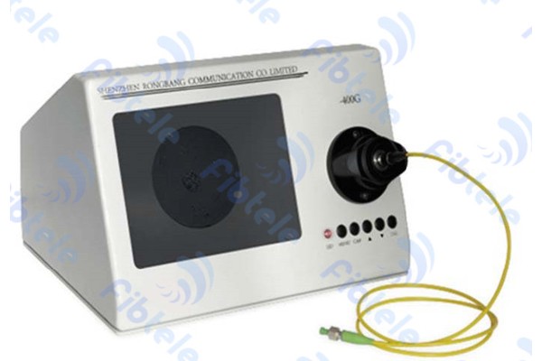
400X Fiber Microscope
Desktop 400X magnification fiber microscope for end-face inspection of fiber optic connectors with image capture capability.
View DetailsRelated technical guides
Primary references
- IEC 61300-3-35 — Visual inspection of connector end faces
International Electrotechnical Commission
- IEC 61755 — Fibre optic connector optical interfaces
International Electrotechnical Commission
Frequently asked questions
Only when compatible fixtures, recipes and consumables are available. Confirm ferrule geometry, polish, pressure and fixture changeover for every connector family.
Quote tested output under stated connector mix, batch size, recipe, operators, yield, inspection and rework assumptions.
It identifies scratches, chips, contamination and geometry issues that can cause high loss or damage a mating interface. Optical testing remains a separate acceptance step.
Send the project inputs for configuration review
Include endpoint models, interfaces, quantities, route or process constraints, required test documents and acceptance criteria.