

5G FTTA Outdoor Fiber Cabling
Plan outdoor fibre assemblies by the radio interface, connector system, route, sealing, bend control and documented field-test criteria.
Technical page updated 2026-07-23
Quick answer
An FTTA cable assembly must match the exact radio and baseband interface, connector system, fibre count, route length and outdoor environment. Mechanical fit, sealing and optical acceptance should be confirmed at the assembly level before field deployment.
Suitable project types
- Outdoor fibre links between baseband, distribution and radio equipment
- Rooftop, tower and pole-mounted radio sites
- Armoured fibre routes exposed to pulling, bending or weather
- Projects comparing pre-terminated and field-terminated assemblies
Inputs required before selection
- 1Radio, baseband and distribution-equipment part numbers
- 2Connector interface, fibre count, port mapping and breakout arrangement
- 3Route length, installation method, bend radius and pulling conditions
- 4Temperature, moisture, UV, corrosion and sealing requirements
- 5Inspection, optical test, labelling and spare-cable policy
Planning workflow
- 1
Verify equipment interfaces
Use current equipment drawings to confirm connector family, keying, port map, fibre count and any licensed interface requirements.
- 2
Survey the route
Record pathway length, entry points, bend locations, strain relief, grounding boundaries and environmental exposure.
- 3
Specify the assembly
Define cable construction, armour, branch lengths, connector protection, labelling, packaging and installation method.
- 4
Set field acceptance
Document inspection, cleaning, continuity, loss measurement and sealing checks for installation and handover.
Selection checklist
- Exact waterproof connector interface and equipment compatibility
- Single-mode fibre type, cable construction and armour requirement
- Ingress, UV, temperature and corrosion requirements for the whole assembly
- Minimum bend radius, pulling load and strain-relief arrangement
- Pre-installation and post-installation test records
Important limits
- A similar-looking waterproof connector is not proof of mechanical or optical compatibility.
- Ingress and environmental performance must be verified for the complete mated assembly, not assumed from one component.
- Hybrid power-and-fibre cables require electrical, grounding and safety review in addition to optical design.
Products mapped to this workflow
These products are relevant to specific stages of the workflow. Final suitability depends on the configuration and acceptance criteria above.
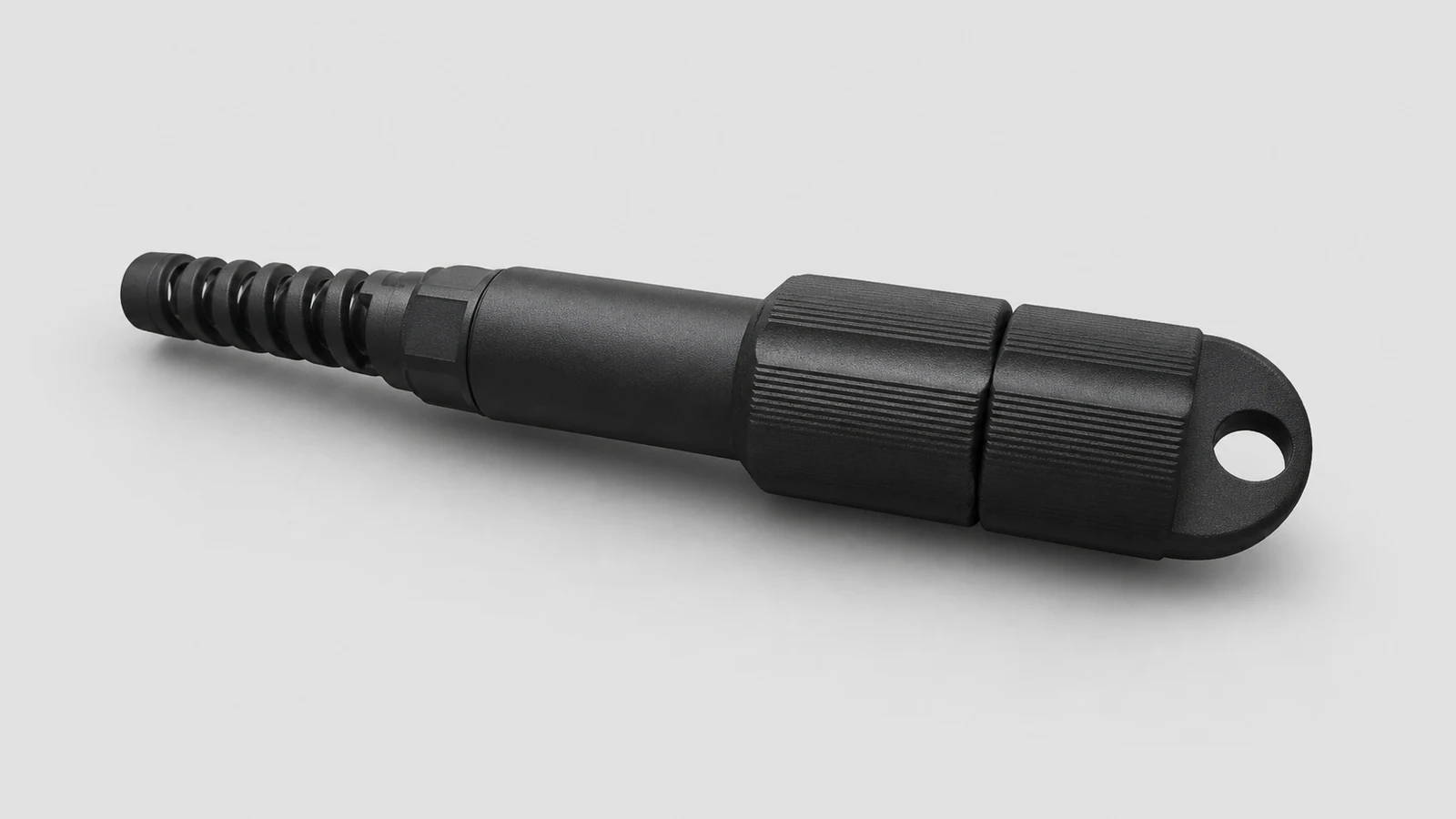
PDLC DX Waterproof Connector
PDLC duplex waterproof fiber optic connector with IP68 protection for outdoor applications.
View Details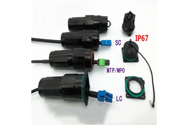
FullAXS New Type
New type FullAXS waterproof fiber optic connector for outdoor FTTA applications with IP67 protection.
View Details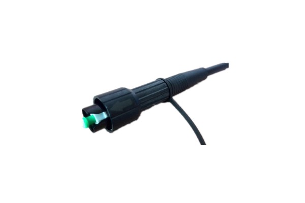
Mini SC
Mini SC waterproof connector with compact design for space-constrained FTTA installations.
View Details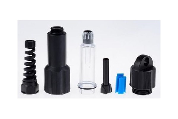
PDLC
PDLC waterproof connector with IP68 rating, suitable for 3.0mm to 7.0mm cable diameter.
View Details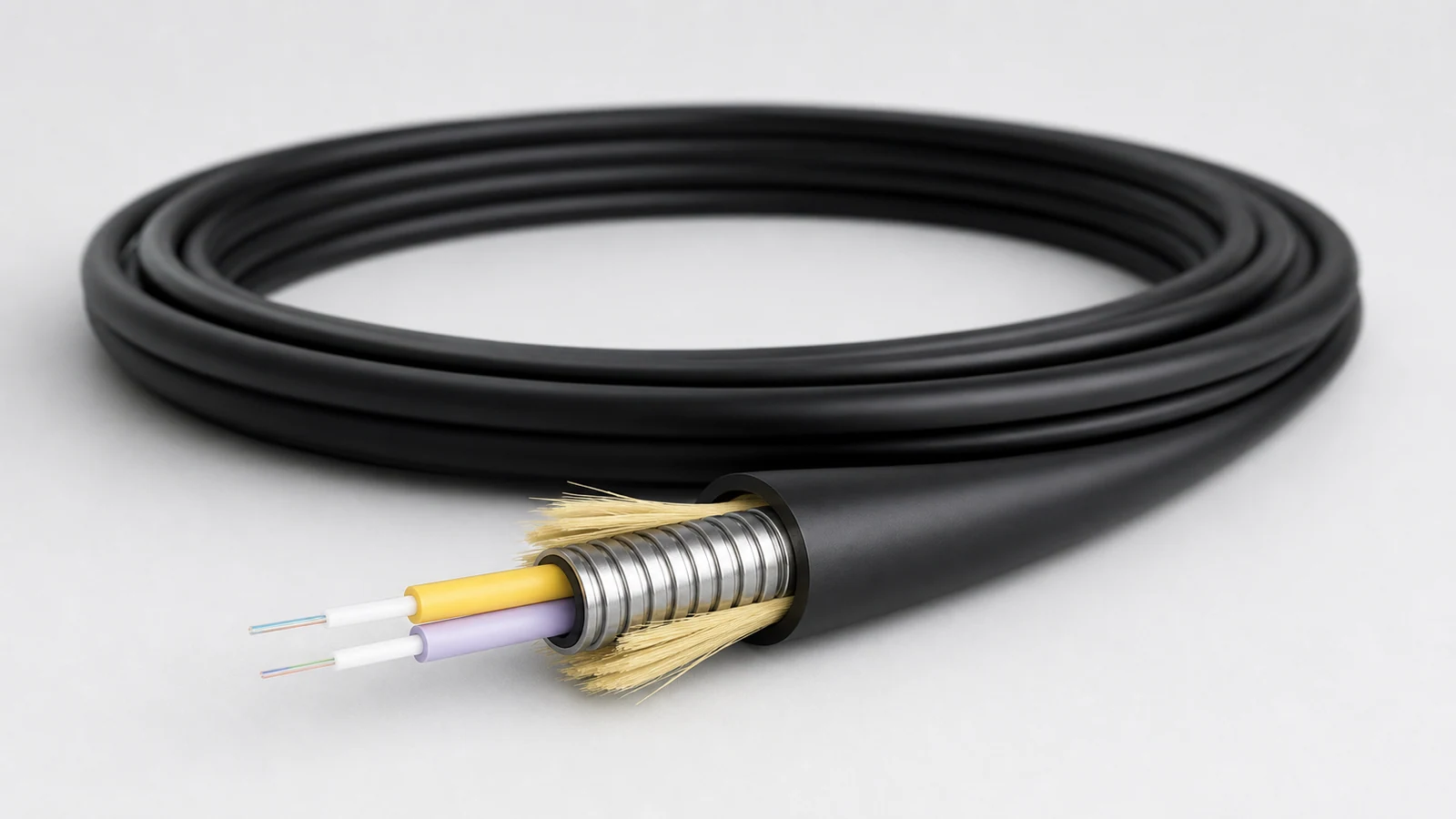
3.0mm DX Armored Indoor Cable
3.0mm duplex armored indoor cable with tight buffer 0.6mm×2 + SUS spiral armored + Kevlar + jacket construction.
View Details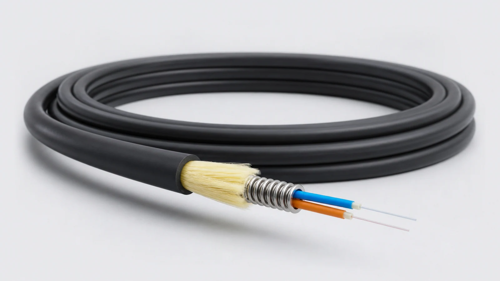
4.8mm 2Fiber Armored Outdoor Cable
4.8mm 2-fiber armored outdoor cable with small diameter, light weight and large capacity data transmission support.
View DetailsRelated technical guides
Primary references
- IEC 62807-3-10:2023 — Outdoor hybrid communication cables for FTTA
International Electrotechnical Commission
Frequently asked questions
Start with the exact radio or distribution-equipment interface and approved mating system. Then verify keying, fibre count, polish, sealing, temperature and cable-entry requirements.
Yes. Define pre-installation inspection and optical test records, then repeat the required checks after routing and mating at the site.
Do not assume so. Confirm the cable jacket, UV, moisture, temperature, mechanical and fire-performance requirements for the actual route.
Send the project inputs for configuration review
Include endpoint models, interfaces, quantities, route or process constraints, required test documents and acceptance criteria.